Forums » Req. WJ2(ESP32) support »
 Serial Monitor Matlab App
Added by Panagis Vovos over 5 years ago
First, I would like to congratulate you on your good work with Waijung 2.
Unfortuatelly, I cannot find some information about how to use the Serial Monitor Matlab App, that you have released lately with it. I am trying to get a view from my control algorithm response using Printf. At some point of my Siumilink schematic I send the output to the printF, because, as it is descrive in the WiKi, it works with the Serial Monitor. However, when I run the Serial Monitor Matlab App and click connect nothing happens. Am I not supposed to get an output like the Serial Monitor found in Arduino's Serial Monitor? Does Serial Monitor creates just the Serial Object and I have to tap my matlab code on that to see the results?
I also tried setting up the UART by instering an UART setup block at 115200 bauds and pins 32/33, but there was nothing again. Am I missing something? Is there information somewhere how to get this printf-Monitor work?
Thanks,
Panagis
Replies (10)
RE: Serial Monitor Matlab App
-
Added by Dhanika Mahipala (ดานิก้า) over 5 years ago
Hi Panagis,
We are glad that you find our product useful.
First see Additional information to see the prerequisites to run the Serial Monitor App. Also you will be able to find other recommended options to view serial data.
If this doesn't help could you please attach the model file where you use the printf block to check the reason for your problem.
Regards,
Dhanika
RE: Serial Monitor Matlab App
-
Added by Panagis Vovos over 5 years ago
Hello Dhanika,
I have all the required prerequisites: Matlab 2020b and waijung2_20.11b. Please find my Simulink schmeatic attached. In this version I have also included the UART setup block, which I do not think it is needed. Initially I have attempted to connect to serial monitor without it, but I got similar results: nothing!
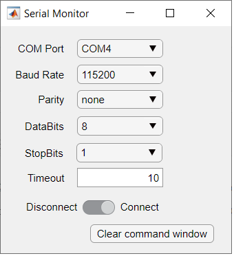
The only thing that happens when I run the Waijung2 Serial Monitor Matlab App, a window opens with the correct COM port preselected, I click connect, but absolutely nothing happens. See the attached file.
The question is where am I supposed to see the results from the printf block in the Simulink schematic? Should it appear in the command window of Matlab?
To be honest I have also tried other serial monitor software (Termite.exe), after setting up the USB serial properly, but still Printf still seams to produce no results.
Any help would be highly appreciated.
Panagis
RE: Serial Monitor Matlab App
-
Added by Dhanika Mahipala (ดานิก้า) over 5 years ago
Hi Panagis,
Sorry for the late reply.
I checked your model and the problem is the way you have used the printf block. Please check the model in the image below.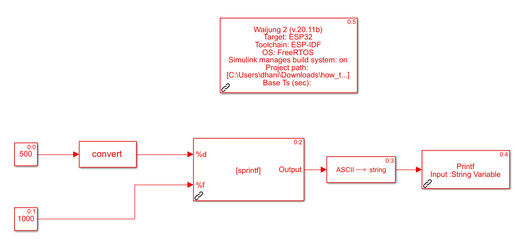
The printf block take a String variable as an input. Therefore we first use String Processing Block to construct the string as required. The output signal of this block is a uint8 array which represent the constructed string. Then use the built in Matlab Simulink block ASCII to String to convert the uint8 to a string signal. Finally you can use the Printf Block block to print your data on the serial monitor.
When using Waijung2 Serial Monitor app after you click connect the serial data should start printing on the Matlab Command Window. For better color coded display you could use a third party Serial Monitor like PuTTY.
You can use how_to_use_printf.slx model file for you to test what is explained above.
Hope this resolves your problem. Do not hesitate to contact us if the problem persist. If possible please attach a screen shot of the model along with the model file itself as it would help respond quicker.
NOTE:
You can check the input/output signal types of each block in the model file by,
right click on the white space of a model file->Other Displays->Signals & Ports->Port Data Types
Regards,
Dhanika
RE: Serial Monitor Matlab App
-
Added by Panagis Vovos over 5 years ago
Hello Dhanika,
Thank you for your reply. Due to your example, it is clear now. However, one more silly, but more general, question popped up by looking at your example:
One printf block outputs 'The values are' and the other outputs 'Value1=... Value 2=...'.
The question is why should the code downloaded on the ESP32 produce 'The values are \n Value1=... Value2=...' and not the other way round, i.e. 'Value1=... Value2=... The Values are \n'?
Thank you - and keep up the good work,
Panagis
RE: Serial Monitor Matlab App
-
Added by Dhanika Mahipala (ดานิก้า) over 5 years ago
Hello Panagis,
If you press Ctrl+D on you keyboard and Update Diagram you will see a small number at the top right corner of each block. Those numbers represent the order in which the generated code of each block is placed in the main program.
If you check the image above you can see that my Value1=... Value2=... string printf has been assigned 0.4 and The values are \n string printf has been assigned 0.7. Therefore my output will first print Value1=... Value2=... and then print The values are \n.
If you want to force the code placement of a block you need to right click on the block and select Properties. Then in the pop-up window named Block Properties you can assign the priority.
A lower priority number means the code generated by that specific block will be placed before the blocks with higher priorities. Priority values can be assigned starting from 0. After assigning priorities you can always Update Diagram to check whether the code generation will be done according to your requirement. Hope this solves your problem.
NOTE:
If you cannot see a number on the top right corner of each block,
right click on the white space of a model file->Other Displays->Blocks->Sorted Execution Order
Regards,
Dhanika
RE: Serial Monitor Matlab App
-
Added by Panagis Vovos over 5 years ago
Hello Dhanika again,
I did my homework, but unfortunatelly, I am still confused with the UART.
In the attached simulink file I create two timer interrupts.
I use the fast one (10kHz) to sample an analog input and output the readings on the Serial port (yes, I used the timer to "overcome" the RTOS ticking limitation of 1kHz). I know this works well, because inside there I also use counters to blink a led every two seconds (1 second on, 1 second off). The led blinks with fantastic precission, which means that the samples are also recovered well from the analog port.
HOWEVER, when I read the samples and the flag for the led from my Serial Monitor, data (samples and flag) is slower than the blinking led. Actually, they start much slower and get faster as time passes BUT they never reach the same speed.
1) How is this possible, since the led blinks perfectly well AND the serial outputs correct, but slow, data? I would suspect that there is not enough time to complete all tasks between interrupts, but this is not possible since I DO get the results.
2) I cannot understand how to set the UART terminators correctly. If I put anything else than <none> as a terminator in the Serial Monitor and the UART TX block (e.g. '0D' for CR) I do not get any data. Why is it double '03 03' in the example presented in the UART block?
Thank you,
Panagis
RE: Serial Monitor Matlab App
-
Added by Dhanika Mahipala (ดานิก้า) over 5 years ago
Hello Panagis,
First of all please use the ADC_high_Sample_Rate_with_CPUprev.slx model file which I modified and download and install Docklight serial monitor software to test the following instances.
TEST 1:
First I changed the interval parameter of Timer Interrupt block to 0.0001 (10kHz) as you have mentioned. The mask of the UART TX block was as follows: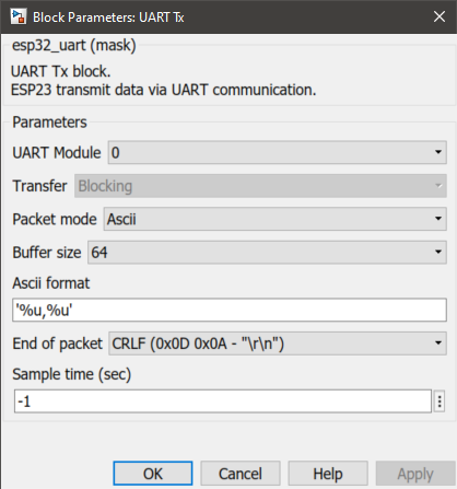
The serial monitor output is as follows: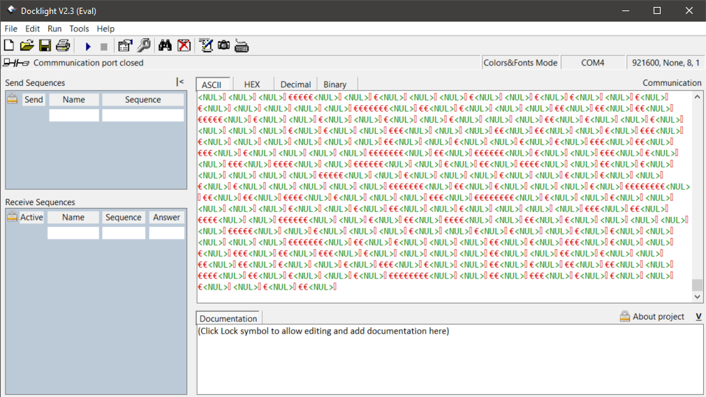
If you replace the UART TX block with a printf block as shown in a previous reply by me, you will see that the system start rebooting continuously (check the image below which was acquired using another serial monitor software called PuTTY). That is because maximum tick rate is 1kHz. 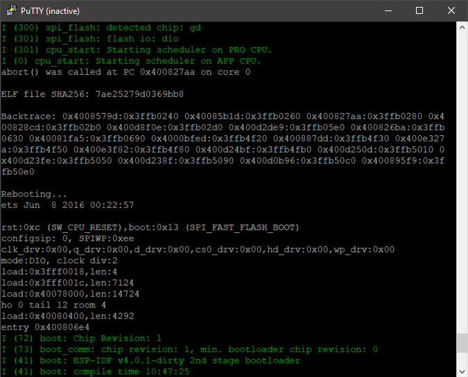
That being said I tested an LED as you've mentioned. For this to work I had to comment both UART TX block and printf blocks. It seems to be working. Even though this worked for this instance (probably because we are directly configuring a hardware peripheral) it is not recommended to operate at higher frequency that 1kHz.
TEST 2:
Next I changed the interval parameter of Timer Interrupt block to 0.001 (1kHz). Note that the Packet mode is set to Ascii for this test. The mask of the UART TX block was as follows:
The serial monitor output is as follows: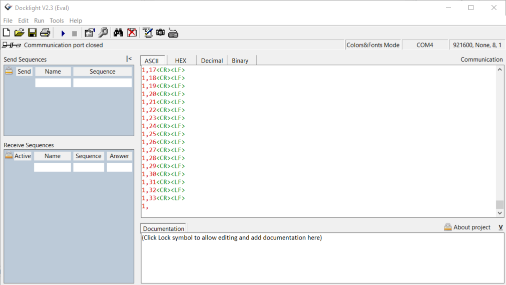
As you can see the output is as expected.
TEST 3:
Since the built in Matlab Serial Receive block can only get binary data over serial port In the above test the Packet mode was changed to Binary. The mask of the UART TX block was as follows: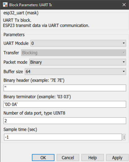
The serial monitor output is as follows: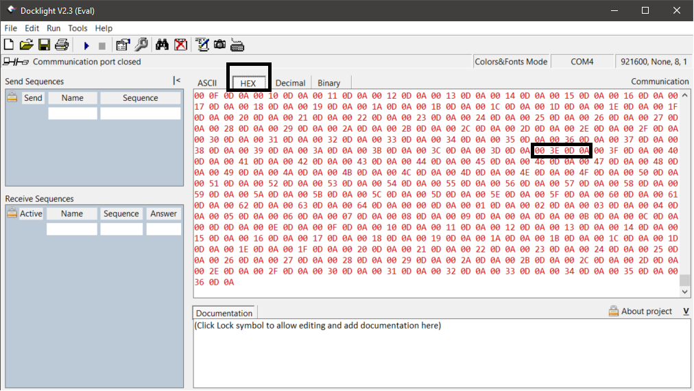
In the image if you check the highlighted part 00 3E 0D 0A, the 00 is the first value which is currently zero and the 3E is the second value which is currently 62 (3E is 62 in decimal). the next two 0D 0A are terminator values CRLF ("\r\n"). This way you could check and see that expected output is shown. Please note that the terminator '0D 0A' is correctly visible from the serial monitor.
NOTE: Please use Docklight or equivalent serial monitor software when testing UART TX block.
Regards,
Dhanika
RE: Serial Monitor Matlab App
-
Added by Panagis Vovos over 5 years ago
Dear Dhanika,
First, I would really like to thank you for your detailed explanation and the time spent.
However, the synchronization/timing question remains. You will have to wait 1-2 hours to see there is a difference between when an action is supposed to happen with the timer interrupt and when it actually happens. Unfortunately, this is not "cured" by the lower interrupt rate; it is just happening with a slower pace.
In order to make myself understood I have prepared a stripped down version of my previous Simulink file that focuses only on the actual timing issue. What it does is simple: A timer is set to tick every 0.001s with the prescaler set to 2 (so that the time interval can be calculated exactly to 0.001s). Every tick enables a function that switches on the GPIO2 led (onboard my Devkit v3) every 1 minute for half a minute (30s on – 30s off etc). Please notice that I do use a “compatible” time interval for the clock interrupt. However, every 10 minutes that pass the led switches on ~1s later than it should, so, for example if you leave the code running on the board for 30 minutes, you will have the led switched on 3s later than it should. If you decrease the timer interval, for example to 0.01s you will have to wait for 30 minutes to clearly notice the delay (~2s). If you make it faster, you will notice it earlier.
I think the problem is indifferent of the 0.001s limitation. It looks like it is reversely proportional to the time interval, BUT certainly has nothing to do with the ticking precision of the 40 MHz crystal, which is 1000X better according to espressif (even in the worst case).
You know better Dhanika, but let me ask
a) Is there is a chance that the timer interrupt is set every sample time(!) and then the board waits for the next interrupt etc, so this adds a small delay every time it is run?
b) If I look under the mask of the clock interrupt block I can see a "timer_pause" variable, but I cannot see the value it has in the code. Does this have anything to do with it?
Thanks again,
Panagis
| Crystaltest.slx | Crystaltest.slx | 31.1 KB |
RE: Serial Monitor Matlab App
-
Added by Dhanika Mahipala (ดานิก้า) over 5 years ago
Dear Panagis,
First of all since this issue is different to the topic of this thread could you please create a new question in the forum and post the above question?
Could you also please state how you observed the said delay ("10 minutes that pass the led switches on ~1s later than it should")? Did you use an oscilloscope or some other method? This information will be helpful for us to debug the issue.
Regards,
Dhanika
RE: Serial Monitor Matlab App
-
Added by Panagis Vovos over 5 years ago
Dear Dhanika,
The issue is the same in substance: timers don't look to me like they work as precisely as they are supposed to (and they are specified to). That is why I (believe I) noticed the delay between timer interrupts and serial port.
I will create another thread, though, to make things easier for you.
Thanks anyway,
Panagis