Forums » Req. WJ2(ESP32) support »
 Bug: Pin settings digital input/output blocks are not correct implemented
Added by Yuttakorn Kaewsuay (รัน) almost 4 years ago
Hello,
I encounter an annoying issue with the digital output pins.
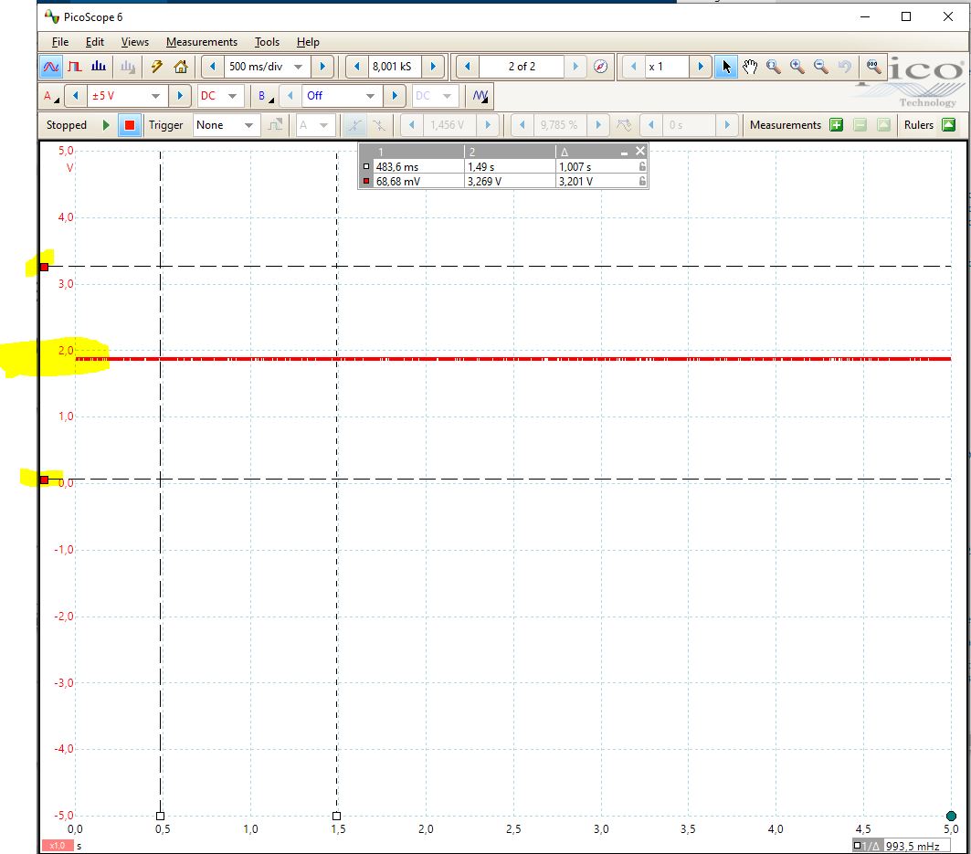
When applying a static constant value to the digital output pin, nothing happens, the pin is in initial state (tri-state).
The connected LED will not turn on, and the output level of the pin will stuck at approx. 2Vdc,
That means, the requested push/pull output is disabled after each write action, so the pin is floating and starts oscillating when move your hand nearby the pins.
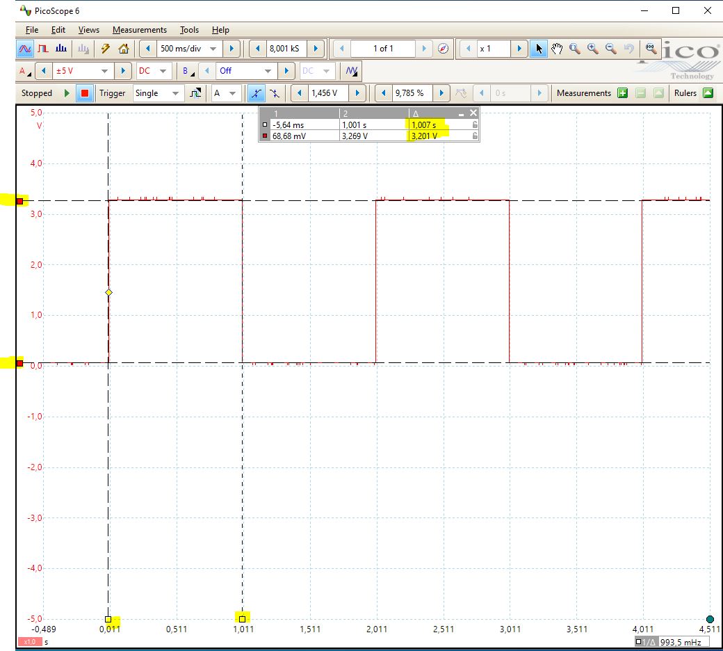
But when replacing the static constant output value with a free running counter, toggling the pin every second, everything works fine.
Also selecting between weak, normal, decent or strongest pushpull, will not result in different behavior.
Hopefully you can find the problem.
Best regards,
Martin.
Replies (5)
RE: Bug: Pin settings digital input/output blocks are not correct implemented
-
Added by Yuttakorn Kaewsuay (รัน) almost 4 years ago
Hello Martin,
Could you please attach the Simulink Model file which this issue is having.
RE: Bug: Pin settings digital input/output blocks are not correct implemented
-
Added by Yuttakorn Kaewsuay (รัน) almost 4 years ago
Hi Chandima,
I've attached 2 different models, one is the dynamic pushpull digital output pin, that works fine so far I can see now.
The second one is the static pushpull model and this result in unwanted behavior.
For both models I used digital output pin IO18 of a ESP32-DEVKIT, that output pin is pulled high with 432 Ohm resistor with a red LED in serial.
In practice the IO pin should sink approx. 5 mA maximum, and this is far below the 20mA of what the eps32 can deliver.
Hopefully you will find the problem and could solve it before the newest release.
Best regards,
Martin.
RE: Bug: Pin settings digital input/output blocks are not correct implemented
-
Added by Yuttakorn Kaewsuay (รัน) almost 4 years ago
Hi Chandima,
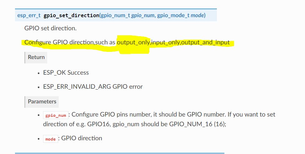
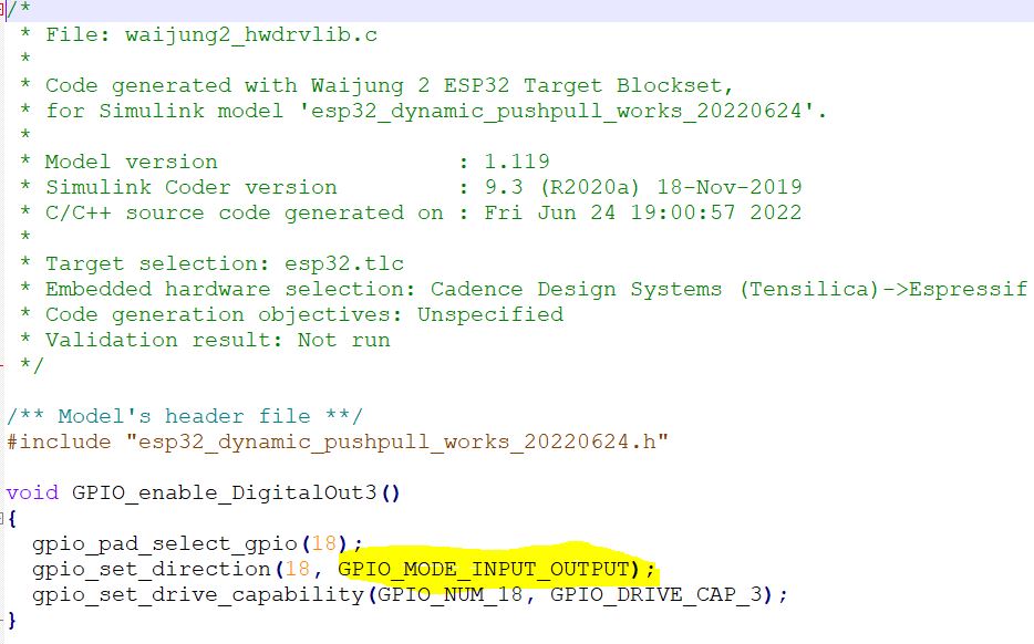
I see in the source code that the digital output pin IO18 is set to "GPIO_MODE_INPUT_OUTPUT", but this should be set to "GPIO_MODE_OUTPUT_ONLY".
See for details the attached pictures.
Best regards,
Martin.
RE: Bug: Pin settings digital input/output blocks are not correct implemented
-
Added by Yuttakorn Kaewsuay (รัน) almost 4 years ago
Hi Martin,
Could you please try by changing the sample time of the constant block to a finite value (-1 or valid sample time instead of having inf) and let me know whether you get the results as you expect.
RE: Bug: Pin settings digital input/output blocks are not correct implemented
-
Added by Yuttakorn Kaewsuay (รัน) almost 4 years ago
Hi Chandima,
Thanks for your answer.
Indeed, changing the default sample time from "infinite" into "inherit" solves the problem.
From then the output pin IO18 is pulled low firmly.
But I've also tested with defining a defined sample time for that fixed/constant block, set it to 1ms, but this will end up in a compilation error.
Is it possible to solve this issue, so the user will not get stuck on a constant block with the default time setting?
That should be great.
Thanks a lot, best regards,
Martin.