Forums » Req. WJ2(ESP32) support »
 High input current for GPIO input pin. No difference in floating, pull up or pull down mode
Added by Johan Henning about 3 years ago
I build the ESP-32 GPIO demo. I tried to pull the input pin (GPIO4) up via a resistor: no success. Then I connected it directly to the 3V3: it works. I measured the input current: 39 mA!
Changing the input pin to pull up or floating does not make a difference, always it draws 39 mA (which is a lot in my opinion). 
20230203: When I add an output block and configure that for GPIO4 I can set the output strength of the output pin. When I set it to weak the input pin current goes down to 10 mA, when I set it to decent is is 20 mA and when I set it to normal it is 39 mA again.
It seems that the input pin is also configured as output pin:
void GPIO_enable_DigitalOutput()
{
gpio_pad_select_gpio(2);
gpio_set_direction(2, GPIO_MODE_INPUT_OUTPUT);
gpio_set_drive_capability(GPIO_NUM_2, GPIO_DRIVE_CAP_2);
}
void GPIO_enable_DigitalInput()
{
gpio_pad_select_gpio(4);
gpio_set_direction(4, GPIO_MODE_INPUT_OUTPUT);
gpio_set_pull_mode(4, GPIO_PULLDOWN_ONLY);
}
Replies (10)
 RE: High input current for GPIO input pin. No difference in floating, pull up or pull down mode
-
Added by martin van beek about 3 years ago
Has Aimagin already looked into this issue?
 RE: High input current for GPIO input pin. No difference in floating, pull up or pull down mode
-
Added by Johan Henning about 3 years ago
No, not yet.
 RE: High input current for GPIO input pin. No difference in floating, pull up or pull down mode
-
Added by Parth Maheshwari (พาร์ท) about 3 years ago
Hi Martin and Johan,
We are looking into this and will update you.
Sincere regards,
Parth
 RE: High input current for GPIO input pin. No difference in floating, pull up or pull down mode
-
Added by Johan Henning almost 3 years ago
Hello Parth,
Have you been able to look into this issue? I don't like the high current when pulling an input pin low.
Regards,
johan.
 RE: High input current for GPIO input pin. No difference in floating, pull up or pull down mode
-
Added by Parth Maheshwari (พาร์ท) almost 3 years ago
Hi Johan,
Currently taking a look. Apologies for the delay of many months. Will update you as soon as there's a solution.
Thank you for your patience.
Sincere regards,
Parth
 RE: High input current for GPIO input pin. No difference in floating, pull up or pull down mode
-
Added by Parth Maheshwari (พาร์ท) almost 3 years ago
Hi Johan,
Thank you for waiting.
We have just released the latest version of Waijung 2 and have fixed the issue you were facing as part of that. Would you kindly upgrade to the latest version to test and let us know if the problem on your end is resolved?

Thank you.
Sincere regards,
Parth
 RE: High input current for GPIO input pin. No difference in floating, pull up or pull down mode
-
Added by Johan Henning almost 3 years ago
Hello Parth,
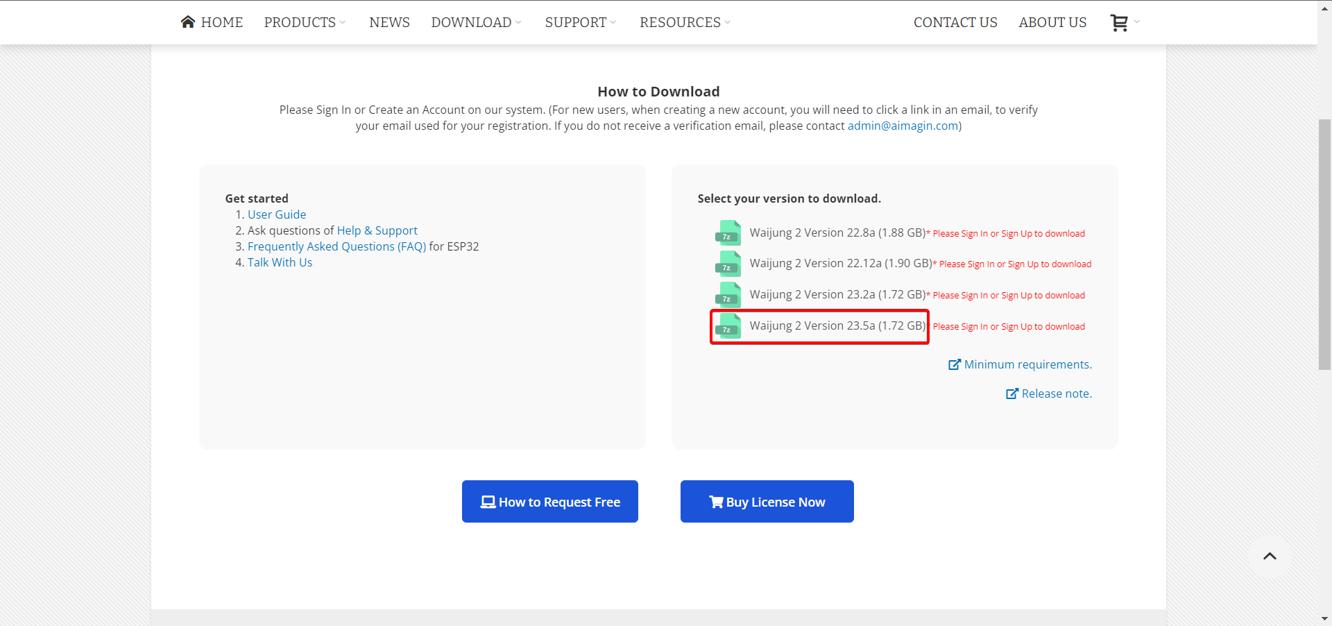
I downloaded and installed the 23.5a version. Now the problem of the high current needed to pull down the input pin is solved. Good work, thanks!
I measure now 0.08 mA when I pull down the input pin which is very nice and which represents an internal resistor of 3.3 / 0.00008 = 41 kOhm. According to the ESP documentation this is correct (The values of the pull-down and pull-up resistors vary from chip-to-chip and pin-to-pin and for the ESP32 are typically in the range of Rup = 30 … 80 kΩ and Rdn = 17 kΩ (pull-down).).
A few aditional questions:
- the first time that I build the project it takes 84 sec. Subsequent builds take 36 sec. I assume this is normal?
- in the previous version the input pin was controlled with this code: gpio_set_direction(4, GPIO_MODE_INPUT_OUTPUT);. Also the output pins were controlled with the same statement: gpio_set_direction(2, GPIO_MODE_INPUT_OUTPUT);. Is there ever a need to configure a pin as input and output at the same time? And if so, how can that be controlled from Waijung? Or is the GPIO_MODE_INPUT_OUTPUT not possible with the toolkit?
- what happens if I configure a pin as input and also as output?
Regards,
johan
 RE: High input current for GPIO input pin. No difference in floating, pull up or pull down mode
-
Added by Parth Maheshwari (พาร์ท) almost 3 years ago
Hi Johan,
1) Yes this is normal. The first build takes the longest because build files need to be created . In subsequent builds, build files already exist so only certain build files need to be updated depending on what has been changed in the Simulink model.
2) In the previous Waijung 2 version, the selected pin could be used as Digital Input as well as Digital Output as you stated. So it is possible. However, while debugging the error you were facing, we realized that pullup, pulldown and float modes don't work when we configure the pin as GPIO_MODE_INPUT_OUTPUT . To work with pullup and pulldown modes, the direction of the selected pins in the Digital Input block should be configured as GPIO_MODE_INPUT, not as GPIO_MODE_INPUT_OUTPUT. Likewise, the pins for Digital Output should be configured as GPIO_MODE_OUTPUT.
As a fix for the issue, if a pin is used in a digital input block, it will be disabled in the digital output block (and vice versa). This is what we have implemented in the latest release . For normal applications, the same GPIO pin will not be used as both Digital Input and Digital Output. So while it's possible, pullup and pulldown modes will not work in this setting. Thus, we have made the trade-off decision to make pullup and pulldown modes work and keep the GPIO pins for Digital Input and Output separate.
One possible application for reading input values from a GPIO pin while also outputting signals to it at the same time is in a sensor-feedback control system. Using a GPIO pin in input/output mode can reduce the overall complexity and cost of a system as the MCU can communicate with both input sensors and output actuators using a single pin, leading to a reduction in number of pins used, wiring, connectors, etc.
3) If you use the Digital Input block, select GPIO2, set the mode as GPIO_MODE_INPUT, and also use the Digital Output block, select GPIO2, set the mode as GPIO_MODE_OUTPUT then this will cause an issue. Assume that the Digital Input Block has the higher priority to execute first, so the pin will be first configured as GPIO_MODE_INPUT and then as GPIO_MODE_OUTPUT. Ultimately, this pin will be configured as GPIO_MODE_OUTPUT. This will result in GPIO2 being an output pin and the Digital Input block will not output anything.
Hope this helps. Please let me know what you think.
Sincere regards,
Parth
 RE: High input current for GPIO input pin. No difference in floating, pull up or pull down mode
-
Added by Johan Henning almost 3 years ago
Hello Parth,
Thanks for the fix and the explanation. The input pins work ok now with the configurable pull-xxx option. So that is ok.
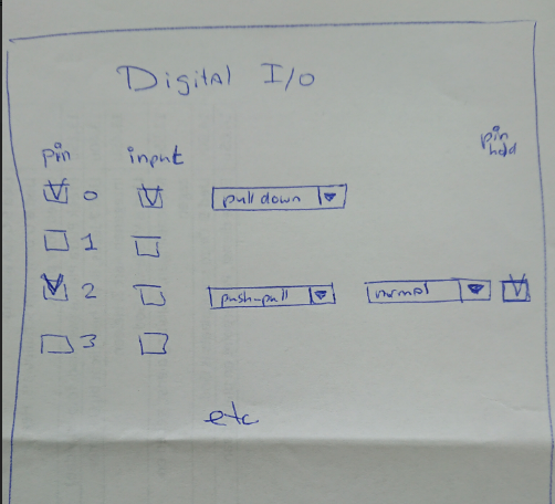
About what I think: In my opinion the input and output blocks should be better combined into one digital I/O block. All available pins should have a checkmark box to turn them on or off and per pin there should be the option to use it as input, output or input/output pin. And also per pin there should be a configuration combobox to set the pull-xxx options or the push-pull and the drive capability options. I think that gives maximum flexibility (which I like).
The digital I/O block lives in the lower layers of the (architectural) model, the driver layer (the HAL (hardware abstraction layer)). So to me it is not a problem to have all the digital I/Os in one (big) block.
It could look like this (see picture). What do you think about this?
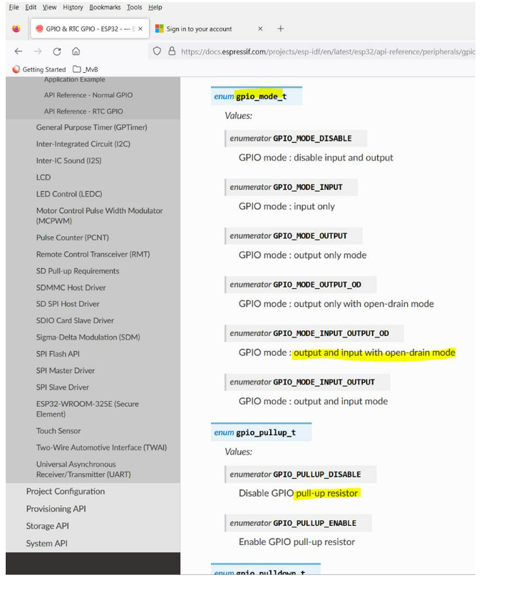
Martin sent me a picture from the expressif documentation with options related to the I/O possibilities. See attached. It would be nice if the toolbox supports all these options.
Regards,
johan.
| clipboard-202305081508-vjnoq.png | View clipboard-202305081508-vjnoq.png | 331 KB | initial idea about combined digital I/O block | ||
| clipboard-202305081509-wlmr9.png | View clipboard-202305081509-wlmr9.png | 291 KB | A few pin modes |
 RE: High input current for GPIO input pin. No difference in floating, pull up or pull down mode
-
Added by Parth Maheshwari (พาร์ท) almost 3 years ago
Hi Johan,
Thank you for the feedback.
We shall take your suggestion into consideration and evaluate whether a single I/O block would serve customers better in the future.
Sincere regards,
Parth