aMG 4-20mA to WiFi Data Logger User Manual
This user manual is for aMG 4-20 mA to WiFi Data Logger with the latest firmware version r3s.21.02c .
Visit aMG 4-20 mA to WiFi Data Logger product page page to purchase the product.
- Table of contents
- 1 aMG 4–20 mA to WIFI Data Logger
- 2 Technical Specifications
- 3 Minimum Requirements
- 4 Hardware Installation
- 5 Device Operation
- 6 Advanced Topics
- 6.1 Factory Reset
- 6.2 Heartbeat Feature
- 6.3 Data Encryption
- 6.4 Removal and installation of micro SD Card
- 6.5 Replacing/Preparing micro SD card
- 6.6 How to retrieve data from micro SD card
- 6.7 How to setup database server to receive data from the device
- 6.8 How to convert UNIX format data to ISO format
- 6.9 Testing data sending to database server
- 7 Appendix
1 aMG 4–20 mA to WIFI Data Logger
1.1 Product Overview
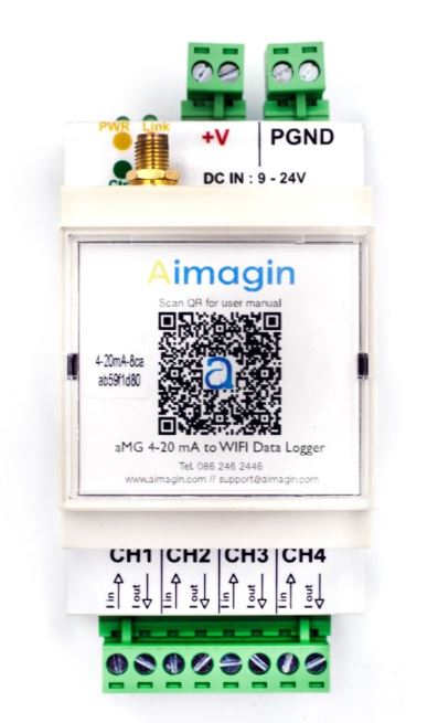
Figure 1-1 : aMG 4–20 mA to WIFI Data Logger
aMG 4-20 mA to WiFi Data Logger is a device that can read up-to 4 channels of 4-20 mA data every 1 second. The data can be encrypted and sent to your own database server securely via WiFi, with 7-years-worth of in-device backup storage. Therefore, you will always have critical information, to the finest detail, stored securely and redundantly both in your own server and in the device.
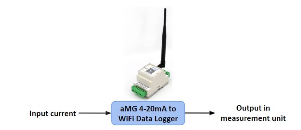
Figure 1-2 : Basic Concept of aMG 4–20 mA to WIFI Data Logger
Installation and usage are simple. No need for data link cabling. No need to collect data on-the-spot. No need to worry about data security and privacy. Just setup your own database server, connect the device to a common WiFi network, and wait for the data to arrive in your database. Most suitable for customer with basic IT knowledge to set up your own database server (free example source code available for our customers).
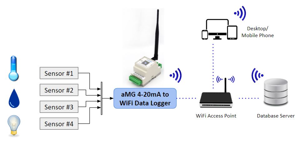
Figure 1-3 : aMG 4–20 mA to WIFI Data Logger work diagram
1.2 Key Features
- Concurrently record all data to internal storage and send data to your own remote database server.
- Support RESTful API webservice with time-varying user-customizable secret-keyed AES encrypted JSON data package.
- Free server setup source code example e.g., Php + MySQL and Node.js + SQLite.
- Easy setup via a web application, just like setting up any WiFi access point at home.
- User and role-based management for device access control by an administrative
- Circular buffer mechanism to ensure precise data acquisition timing.
- Configurable heartbeat service for data connection health checks.
- Over-the-Air firmware upgradable to take advantage of new features in the future.
2 Technical Specifications

Figure 2-1 : aMG 4–20 mA to WIFI Data Logger Size
- Enclosure
- DIN rail fitting.
- 100 % ABS FR Flame Retardant UL94V-0 plastic material.
- Power supply
- Voltage range: 9 – 24 VDC.
- Maximum current consumption: 200mA.
- Mispolarity voltage protection.
- Over voltage protection.
- Inputs
- Current loop (4-20 mA): 4 channels.
- Sample time interval: 1 second – 24 hours (can be independently set for each channel).
- Connectivity
- 11 b/g/n (2.4 GHz), up to 150 Mbps.
- Support RESTful webservice for sending data to server with user customizable JSON field name.
- SMA (female) antenna connector.
- Built-in backup storage
- Replaceable micro SD card (16GB supplied with the device – can store up-to 7-years-worth of all 4-channels data at 1Hz sampling rate).
- Support micro SD card up to 32GB (recommended Class 10 micro SD card).
- Backup data can be downloaded wirelessly on-the-spot.
3 Minimum Requirements
According to the hardware specifications, aMG 4-20 mA to WiFi Data Logger has the minimum requirements as following:
- 9 - 24 VDC Power Supply
- 4-20 mA signal sources (the device supports up to 4 input signals)
- WiFi network
- Database server with RESTful API web service
4 Hardware Installation
4.1 Hardware Components

Figure 4-1 : Hardware Components
Table 4-1 : aMG 4-20 mA to WIFI Data Logger's Components
| Component | Functions | Description |
| A | Power supply VCC | Port, to connect to the power supply VCC (9 – 24 V). |
| B | Power supply GND | Ports, to connect to the power supply ground. |
| C | Input channels | Ports, to connect to sensors, support up to 4 sensors. |
| D | Router antenna | WiFi router antenna. |
| E | LED indicator | A power status indicator and operating status indicator (see Operating LED Indicator). Other two LEDs are not available. |
| F | Antenna connector | Antenna input connector. |
| G | Enclosure locks | Case lock. It can be opened to insert the micro SD card or other internal components. |
4.1.1 Operating LED Indicator
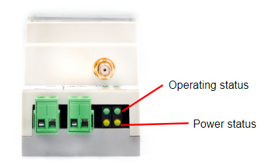
Figure 4-2 : Operating LED Indicator
As mentioned in previous section, there're only 2 LED available as shown in the figure above. The power status is indicated by the yellow LED, while the green LED shows the status of the operating condition with blink in different frequency. The meaning of each LED freequency is defined as following:
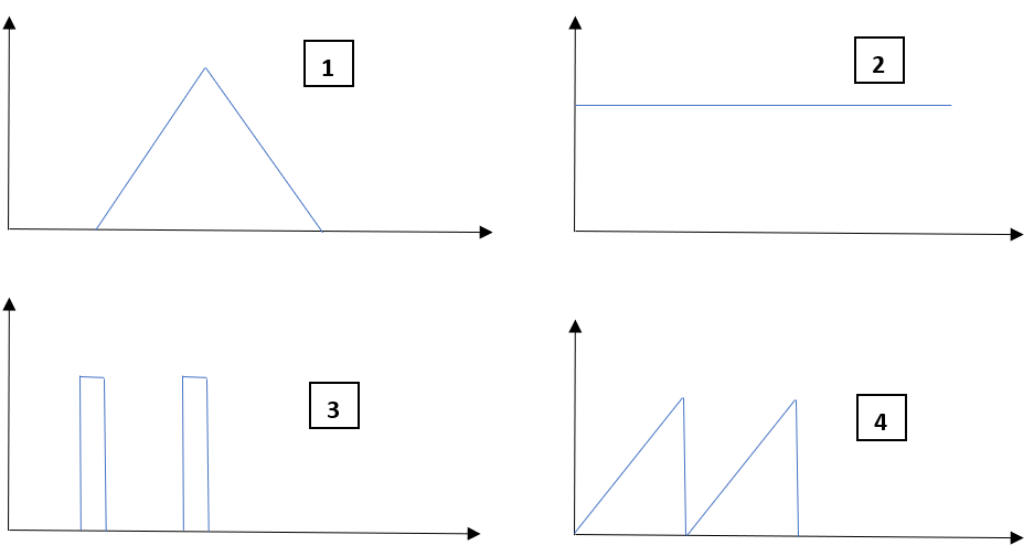
Figure 4-3 : LED Blink
Table 4-2 : aMG 4-20 mA to WIFI Data Logger LED Status
| No. | Operation Mode | Condition | LED Indication |
| 1 | Access Point (AP) /Configuration Mode | available for connection from a user, no connection or trying to connect |  blink 1 Hz blink 1 Hz |
| 2 | Access Point (AP) /Configuration Mode | user connected successfully |  solid solid |
| 3 | Station Mode (STA) /Running Mode | trying to connect to a WIFI access point |  blink 5Hz blink 5Hz |
| 4 | Station Mode (STA) /Running Mode | successfully connected to a WIFI access point |  2 fast blink and 1 sec OFF 2 fast blink and 1 sec OFF |
4.2 Installation
Components, refer to the Figure 4-1
- install the router antenna (D) to the antenna connector (F) on the device.
- connect the sensors to the input channel (C)
- connect the power to the +VCC (A) and GND (B) of the device, it will start automatically (the power status indicator (E) will light up).
- Reversed power connection causes the device does not work.
- Getting minus value from the device may occur when connect the sensor reversely.
Tips: Scan QR Code on the device for more information or any helps.
5 Device Operation
aMG 4-20 mA to WIFI Data Logger has two operation mode which is Configuration Mode and Running Mode.
5.1 Configuration Mode
Setting the aMG 4-20 mA to WIFI Data Logger can be done easily in the configuration mode via web-application by using a desktop computer or mobile phone.
5.1.1 To access Configuration Mode
Step 1 Connect the power supply to aMG 4-20 mA to WIFI Data Logger.
Step 2 Disconnect WIFI on your desktop and connect your desktop or mobile phone to the device through WIFI connection by selecting the device name 4-20mA-<UID> in the WIFI setting as figure below. The password is 12345678.
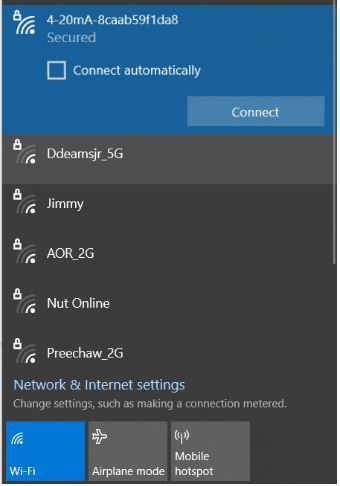
Figure 5-1 : Connecting the device
Note: This step shall be done within 60 seconds after connecting the device to power supply. After 60 second without connection, it will work as running mode automatically. To attempt to configuration mode, you need to disconnect the power supply and re-connect again. Then the device will switch to configuration mode again.
Step 3 Open a web browser, then go to the URL:
192.168.10.10The Aimagin Analytics login page will appear as figure below.

Figure 5-2 : Aimagin Analytic login page
Step 4 Login by using username as admin with the password 1234 . After logging in, the configuration page will pop up. The device is in the configuration mode now. User can see the configuration tab at the left as following:
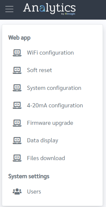
Figure 5-3 : Configuration Tab
5.1.2 WiFi Configuration
Before using, user need to select the WiFi access point for the device by filling the information as shown below.
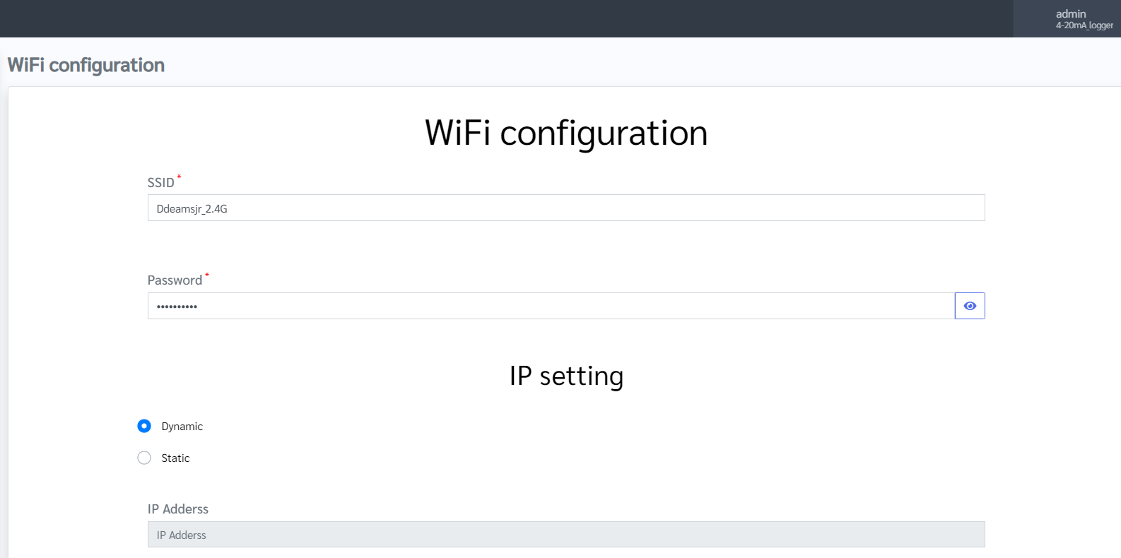
Figure 5-4 : WiFi Configuration
- Identify SSID as your WiFi or network name. Then fill in the password of your network.
- Click on update button to save the WiFi setting. Once the update complete, there is a pop up message below.
Figure 5-5 : Update complete message
Note: For IP setting, Dynamic is recommended. However, it depends on user security policy.
5.1.3 Soft Reset
In this tab, user can do Soft Reset by clicking Reset button.
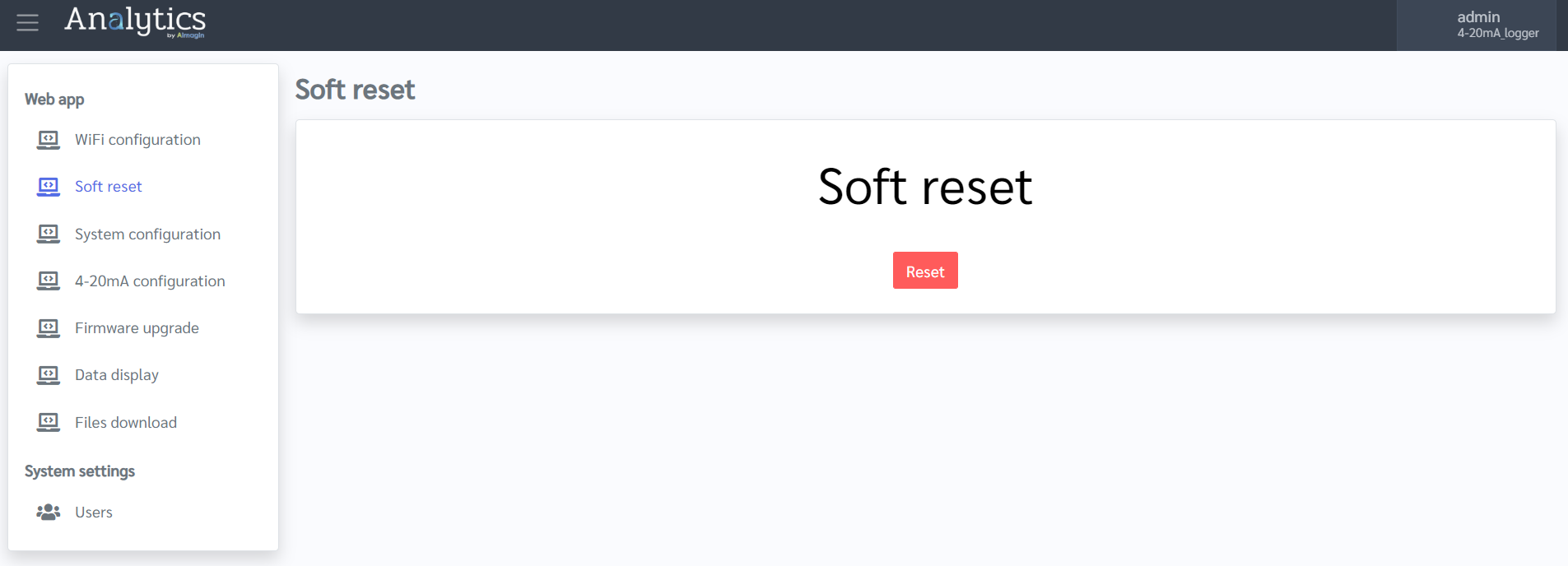
Figure 5-6 : Soft Reset
After clicking Soft Reset button, there is a pop up message for confirmation as below figure, then click OK.
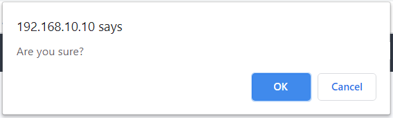
Figure 5-7 : Soft Reset Confirmation Message
Once the device is soft reset completely, a message appears as following figure.
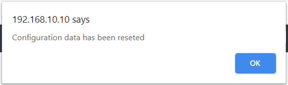
Figure 5-8 : Soft Reset Complete
For more information, see Soft Reset
Note: Soft reset function will lose all configuration data, make sure that user backup the data before doing reset.
5.1.4 System Configuration
In this menu, user can find the Device UID and its Firmware version here. In additions user can set the sample time of channel the target server to send out data to the database, and JSON format parameters as a default data format.
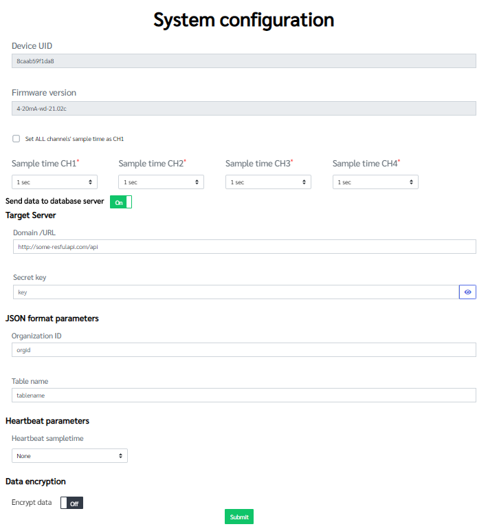
Figure 5-6 : System Configuration
- Sample time
Setting the sample time of each channel which indicate the time period of data sent to target server:
Select the sample time from the drop-down list. To customize the sample rate, you can also select custom to specify the sample rate that you desire. - Target server
Fill the domain or IP address and Secret key for the target server information. - JSON format parameters
Identify organization ID and Table name as a basic information of the data set.
For more information regarding JSON format, see Default JSON Format - Heartbeat sample time
To set the heartbeat sample time for the Heartbeat feature, see more Heartbeat Feature. - Encrypt Data
To turn on/off encrypting data to protect the collected data. For more details, see Data Encryption
If user turn on Encryption Data, the Encryption Key is required.
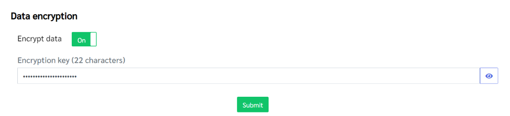
Figure 5-7 : Turn On Encryption Data
To save all setting in this page, click on Submit, then the update status message will pop up as figure 5-5.
5.1.5 4-20 mA Configuration
This menu is for configuring the input/output signal conversion.

Figure 5-8 : 4-20 mA Configuration
- Select the input Channel which you would like to configure.
- Set the Name to represent the input signal, e.g., Pressure.
- Set the Units for the output signal, e.g., MPa for a pressure sensor.
- Define the coordinate of Point 1 (min point) and Point 2 (max point), see figure 5-9. After providing the coordinate of two points, the system will calculate the linear equation conversion according to your setting.
Once user provide all information above, to save all setting in this page, click on Submit, then the update status message will pop up as figure 5-5.
To understand the concept of 4-20 mA Signal Conversion, see the figure below:
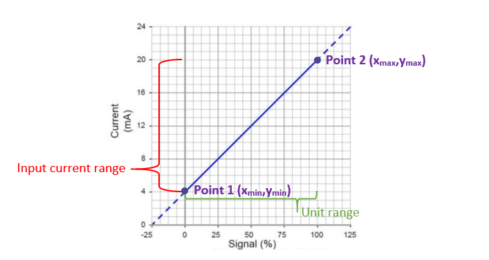
Figure 5-9 : 4-20 mA Conversion
5.1.6 Firmware Upgrade
Once the new firmware available, user can purchase for the firmware to upgrade the device via the Firmware upgrade section.
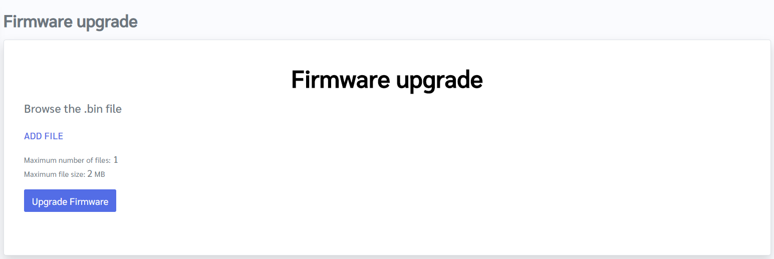
Figure 5-10 : Firmware Upgrade
When user get the new firmware (.bin file), just follow the step below:
- Click ADD FILE to browse the downloaded firmware from your desktop.
- Then click Upgrade Firmware to upgrade the device.
- Once the firmware completed upgraded, there is a message pops up, click OK. The device will reboot itself.
After firmware upgraded, user needs to download new file (.7z) to replace all file in micro SD card.
- Download the 4-20mA-wd-<version number> .7z (the correct file corresponding to the correct firmware version in use), from the product page.
- Extract the .7z file and copy the following files to the root directory of the micro SD card. Do NOT put the extracted files inside a sub directory in the micro SD card. To prepare remove and prepare micro SD card, see Removal micro SD card and Preparing micro SD card.
Note: In case of firmware upgrade, both configuration data and sensor data will be lost. Make sure that user back-up the data before upgrading.
5.1.7 Data Display
This menu to show the data display for each channel in real time according to user settings.
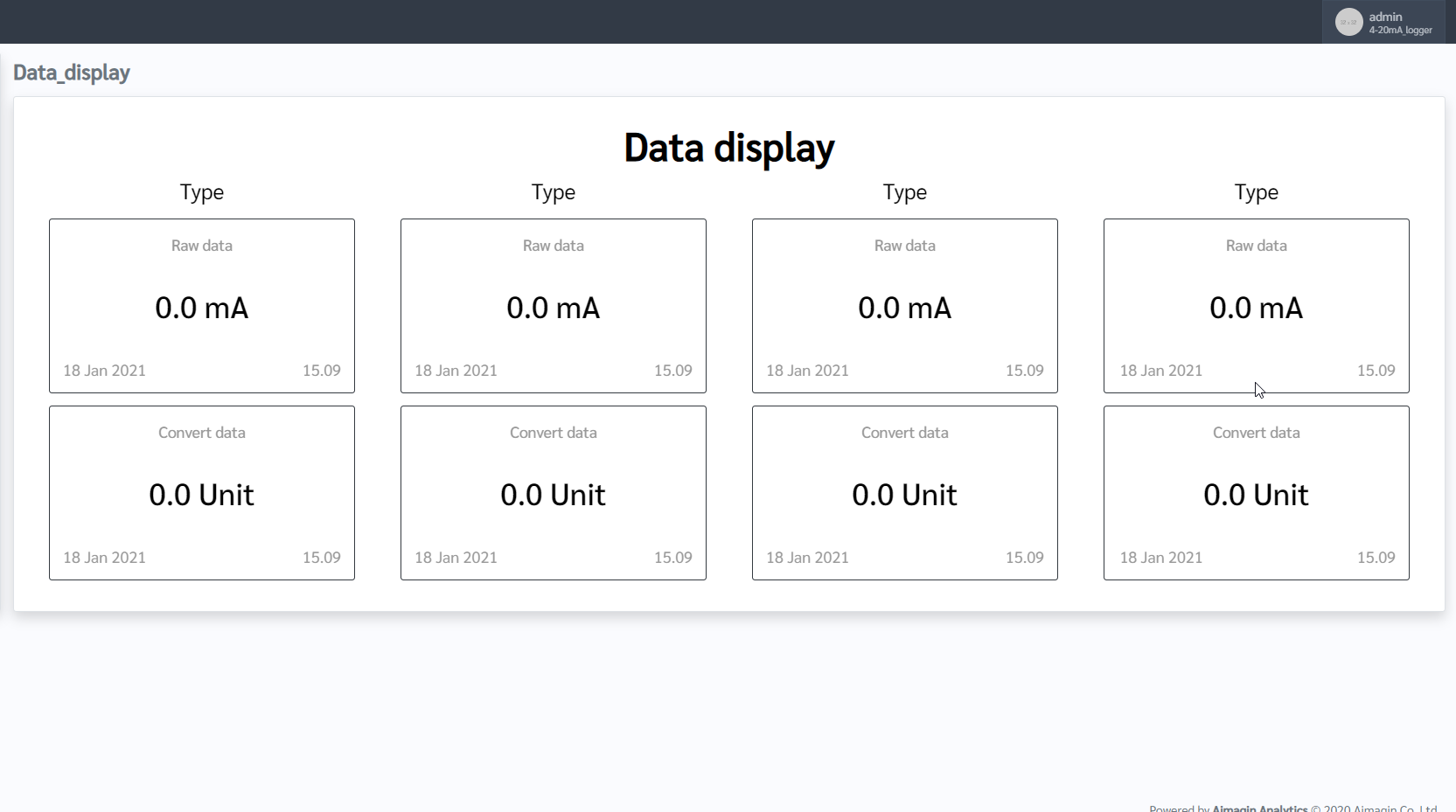
Figure 5-11 : Data Display
5.1.8 Files Download
This feature is for downloading the sensor data which collected by the device. There are two options to download, i.e. database and log file format.
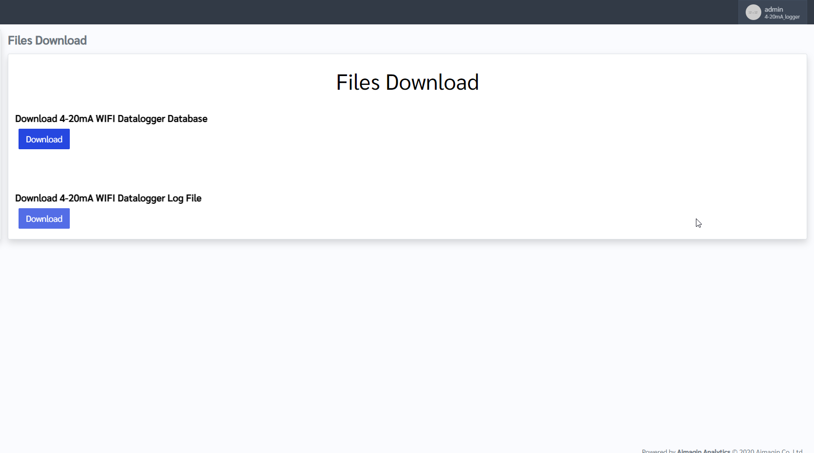
Figure 5-12 : Files Download
5.1.9 User Management
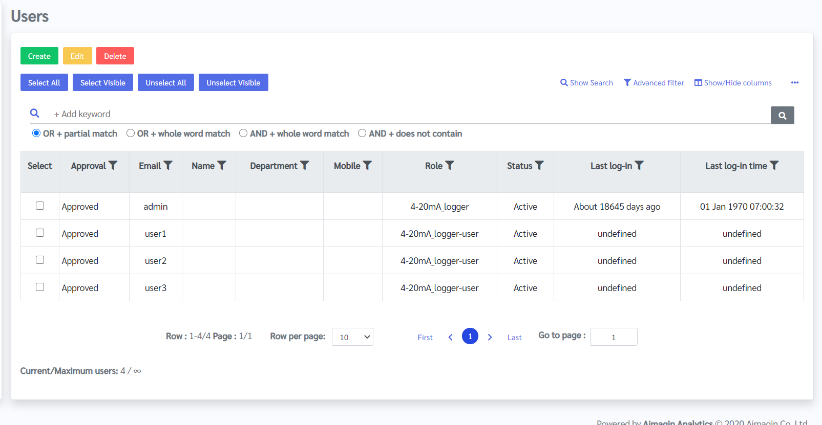
Figure 5-13 : User Management
In Users menu, user will find user list and their log-in history to the device. You can manage users and their permission to access device configuration under this menu.
- To edit or modify the existing users data and their roles, select the user you would like to manage, then click on Edit button.
- To delete user, select user you would like to remove, then click on Delete button.
- To add new user, click on Create button, it will lead to user creation page as figure below, then provide user information and set user password for logging in to the configuration mode. Once finishing, click Update/Approve.

Figure 5-14 : To create user
5.1.10 Exit from Configuration Mode and start Running Mode
To exit the configuration mode or start the device in running mode:

Figure 5-15 : Log in Profile tab
Click on the admin login profile at the right corner of the web page, then click log out.
Note: If there is no active in configuration mode for 60 seconds, it will end the configuration mode and start running mode automatically.
5.2 Running Mode
When turn on the aMG 4-20 mA to WIFI Data Logger, it will run in Configuration mode automatically. To end up the configuration mode and switch to Running mode respectively.
In Running mode, aMG 4-20 mA to WIFI Data Logger will use the predefine configuration parameters according to the user setting. After the setup, the device will perform the following steps:
- Take measurements of ALL four input channels at the specified sample time according to the System Configuration.
- Convert the 4-20 mA raw readings to physical values as specified by the data conversion settings, see 4-20 mA Configuration.
- Save both raw date and converted data to aMG 4-20mA database on device's micro SD card.
- Send both raw and converted data to the remote database server specified in settings.
6 Advanced Topics
6.1 Factory Reset
6.1.1 Soft Reset
This type of reset is to reset only the configuration setting, i.e. the configuration data will be erased while the collected data from sensor still remain.
6.1.2 Factory Reset
The factory reset is to reset all data stored in the device, both confuguration data and collected data. Therefore, user need to backup log data before doing factory reset.
For aMG 4-20 mA to WIFI Data Logger, Factory Reset can be done by formatting the micro SD card then copy the server inintial file to the micro SD card which is the same method of Preparing micro SD Card.
6.2 Heartbeat Feature
This feature is for checking whether the device still work and collect data properly during running mode. In case the long length sample time, using this heartbeat feature, user don't need to wait until the next data arrives according to the sample time for each channel because this feature will allow the device collect data earlier than the actual sample time, i.e. the heartbeat feature will let the device to collect sensor data according to the Heartbeat sample time, which shall be less than the sample time for each input channel. If the device works properly, user will see the data before sampling period.
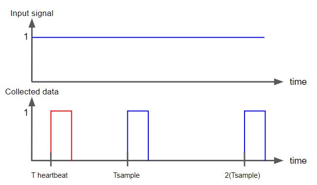
Figure 6-1 : Heartbeat feature concept
6.3 Data Encryption
Encryption is a process of converting the valuable data or plaintext into an alternative form of data which is called as a ciphertext . It is used to secure the sensitive data when sending from one device to another. Encryption is performed using an encryption key and that key can be accessible for authorized persons. The ciphertext can only be converted to the plaintext using the same encryption key which is used to encrypt the data. There are different types of encryption methods to encrypt and decrypt the data.
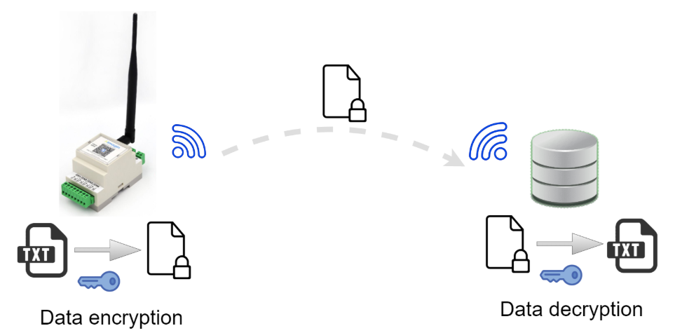
Figure 6-2 : Data Encryption and Decryption
aMG 4-20 mA to WIFI Data Logger has the capability to encrypt the data in AES CBC method. It is using an encryption key with the size of 256 bits (32 bytes). This 32 byte key is dynamically changed from time to time and it is formed with the combination of the time when sending the data and a static key (22 bytes). That static key should be specified in the system configuration page of configuration mode. In the encryption process, the default JSON package converted to a ciphertext and put it in to another JSON package with datetime, organization id and sent it to the database server. The sample JSON package after the encryption will be as below.
{
   "id":"xxxxxxxx",
   "encrypt_data":"xxxxxxxxxxxxxxxxxxxxxxxxxxxxxxxxxxxxxxxxxx",
   "datetime":"xxxxxxxxxx"
}
- id: Organization ID, by default it will be orgid. This can be changed in System Configuration page of the Configuration mode, see System Configuration..
- encrypt_data: The encrypted JSON packaged will be included here.
- datetime: datetime represents in the UNIX format.
6.4 Removal and installation of micro SD Card
To remove micro SD card, see the following steps:
Step 1 Open the case by unlocking the enclosure lock, see component G, Figure 4-1.
Step 2 Lift the FiO Glide ESP32 board (the upper board) from the main board as shown in figure 6-3.

Figure 6-3 : Removal micro SD card
Step 3 micro SD card is installed at the back of FiO Glide ESP32 board. Push the micro SD card to remove it.
6.5 Replacing/Preparing micro SD card
Once user wants to replace the micro SD card with the new one, perform the following steps:
Step 1 Remove the old micro SD card, see Removal and installation SD Card.
Step 2 Format the new micro SD card using FAT32 file system.
Step 3 Copy all files and folders from the old SD card as shown in the figure below to the new micro SD card. If not all files and folders appear as shown in the figure, try view hidden files in Windows Explorer setting.
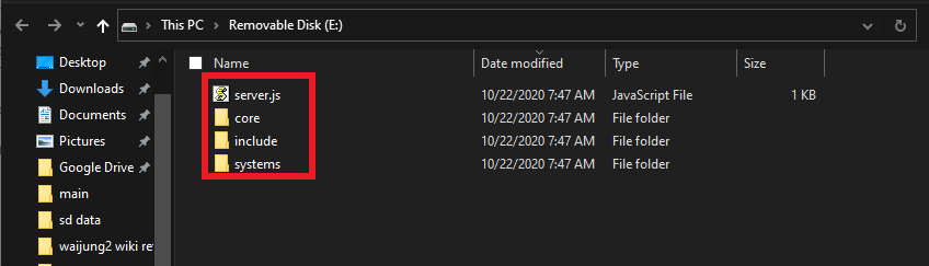
Figure 6-4 : Preparing micro SD card
Step 4 Insert the new micro SD card into the device, see Removal and installation of micro SD Card.
6.6 How to retrieve data from micro SD card
6.6.1 Review data using DB Browser for SQLite
The SQLite database in the micro SD card serves as a backup and could be accessed anytime by following the steps below.
Step 1 Remove the micro SD card from the device as described in Removal and installation of micro SD card.
Step 2 Attach the micro SD card to a micro SD card reader and connect it to the computer.
Note: make sure that the micro SD card reader/adaptor is set as unlock when it is inserted into the computer, otherwise user cannot change or manage any files in the micro SD card.
Step 3 Download and install DB Browser for SQLite
Step 4 Open DB Browser for SQLite.
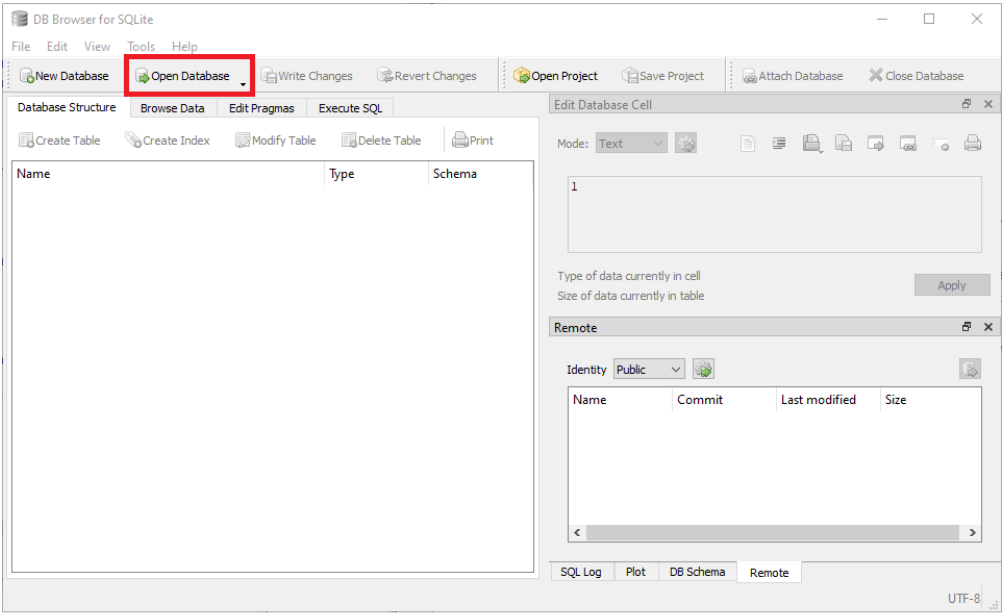
Figure 6-5 : SQLite database
Step 5 Click Open Database . Browse and select the .../systems/system1/database.db file in the micro SD card.

Figure 6-6 : Browse database file
Step 6 Click the Browse Data tab and select the Table : data_table. Here you can find the saved data from the device.
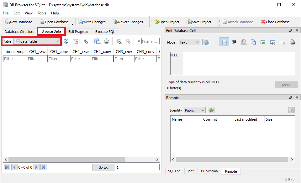
Figure 6-7 : Data table
Step 7 To use an SQL query to filter data, click Execute SQL tab, type the command and click run icon
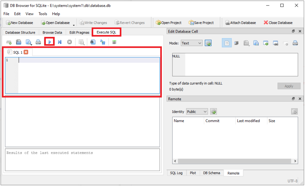
Figure 6-8 : Filter data
Note: The data stored in micro SD card are always stored with UNIX timestamp. To analyze data in human-readable date time format, see How to convert UNIX format data to ISO format.
6.6.2 Export the database as a CSV file
Raw data is stored in data_table table of the database.db, which can be exported as a CSV file using the following steps:
Step 1 Open the * database.db * file with DB Browser for SQLite.
Step 2 Select File->Export->Table(s) as CSV file...
Step 3 Select the table: * data_table * and click * Save * .
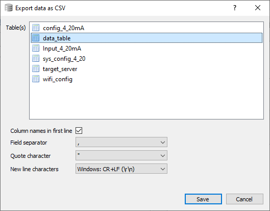
Figure 6-9 : Export CSV file
Step 4 A window will pop up where you could select the name and location of the CSV file to be saved.
Step 5 User could use Microsoft Excel or any other similar software to open the CSV file.
6.7 How to setup database server to receive data from the device
6.7.1 Default JSON Format
The JSON format of the data which sends from the device to the database server is as below.
{
   "mac":"xxxxxxxxxxxx",
   "id":"xxxxxxxx",
   "table":"xxxxxx",
   "column":[
      "datetime",
      "CH1_raw",
      "CH1_conv",
      "CH2_raw",
      "CH2_conv",
      "CH3_raw",
      "CH3_conv",
      "CH4_raw",
      "CH4_conv"
   ],
   "rows":[
      {
         "datetime":"xxxxxxxxxx",
         "CH1_raw":0.000,
         "CH1_conv":0.000,
         "CH2_raw":0.000,
         "CH2_conv":0.000,
         "CH3_raw":0.000,
         "CH3_conv":0.000,
         "CH4_raw":0.000,
         "CH4_conv":0.000
      }
   ]
}
- mac: MAC address of the device.
- id: Organization ID, by default it will be orgid. This can be changed in System Configuration page in the Configuration mode, see System Configuration.
- table: The name of the table in the database server which the data is being inserted. This can be changed in System Configuration page in the Configuration mode.
- column : Column names of the table in the database server. Those columns cannot be customized. Columns should be datetime , CH1_raw , CH1_conv , CH2_raw , CH2_conv , CH3_raw , CH3_conv , CH4_raw , CH4_conv
The data types of each column as below- datetime: TEXT
- CH1_raw: TEXT
- CH1_conv: TEXT
- CH2_raw: TEXT
- CH2_conv: TEXT
- CH3_raw: TEXT
- CH3_conv: TEXT
- CH4_raw: TEXT
- CH4_conv: TEXT
- rows: Includes the row data with corresponding column names. It can be an array of multiple row data.
- datetime: datetime represents in the UNIX format.
6.8 How to convert UNIX format data to ISO format
The timestamp of the data stored in micro SD card is in UNIX format for efficiency. To easily analyze the data the user could use the DB Browser for SQLite.
Step 1 Open the micro SD card using windows explorer and copy the .../systems/system1/database.db file in the micro SD card to a known location. This step is taken as a precaution to not alter the actual data table in the micro SD card as it could lead to device malfunction.
Step 2 Download and install DB Browser for SQLite
Step 3 Open DB Browser for SQLite.
Step 4 Click Open Database . Browse and select the database.db file saved at the known location during Step 1 .
Figure 6-10 : SQLite database
Step 5 Click the Browse Data tab and select the Table : data_table. Here you can find the saved data from the device.
Figure 6-11 : Data table
Step 6 Go to Execute SQL tab. The user can now use any SQLite query to filter the data in the table as needed.
Here are two examples on handling UNIX time format.
Step 7 Create an additional column next to datetime column called date_iso which corresponds to the datetime in ISO format of each UNIX format timestamp.
SELECT datetime,
datetime(datetime, 'unixepoch', 'localtime')
AS date_iso,
CH1_raw,
CH1_conv,
CH2_raw,
CH2_conv,
CH3_raw,
CH3_conv,
CH4_raw,
CH4_conv
FROM data_table
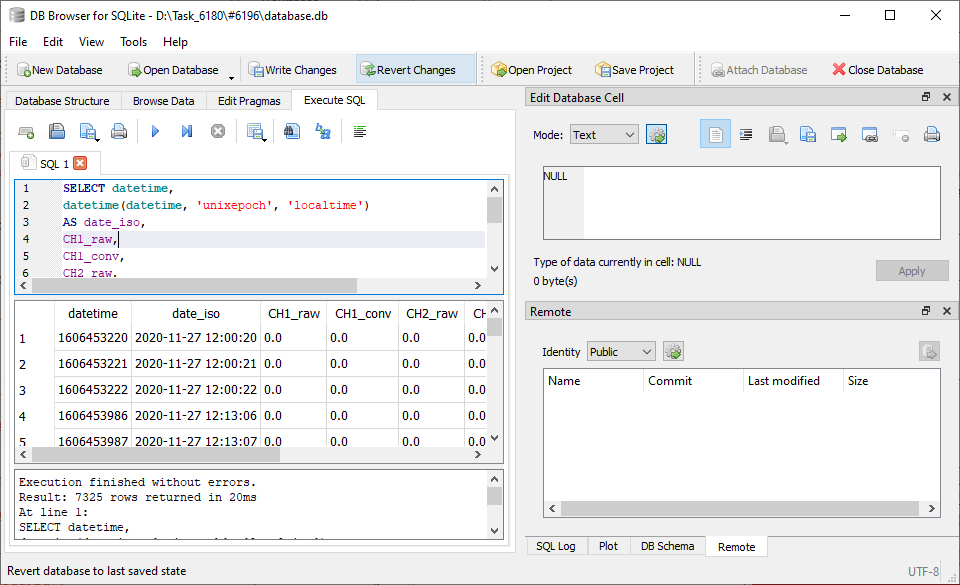
Figure 6-11 : UNIX format data
Step 8 Filter out rows of sensor data which are in between two timestamps, specifying the date and time in ISO format.
select timestamp,CH1_raw
from data_table
where datetime(timestamp, 'unixepoch', 'localtime')
between '2020-10-22 18:15:30' and '2020-10-22 18:18:30';
6.9 Testing data sending to database server
This section provides information regarding testing sending data from aMG 4-20 mA to WIFI Data Logger to a database server.
The purpose of the test is to ensure that the device can transfer the collected data to a database server properly. User can test the device as the following steps:
Step 1 Since the database server is required, user needs to register for a database which shall be the target server for the device via the following URL: http://testiot.aimagin.com/register
The register page will be loaded as shown in Figure 6-12.
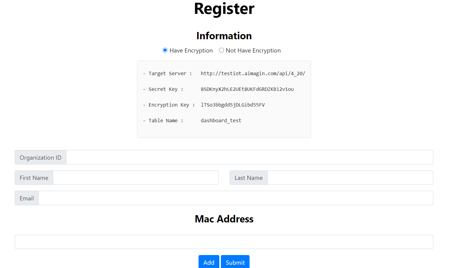
Figure 6-12 : Register Page
Step 2 Select data encryption option, then provide your Organization ID, First Name, Last Name, Email, and MAC Address (12-digit UID of the aMG 4-20mA to WIFI Data Logger)
Note: User can add MAC Address for many devices at once.
Step 3 Click on Submit, the Register Success page will be loaded. The page contains some necessary configuration data, i.e. Target Server domain, Secret Key, Encryption Key (In case user select encryption option), and Table name as shown below.

Figure 6-13 : Register Success
Step 4 Go to system configuration and set configuration data according to the data in Register Success page, then click on Start Test. The data table will appear as below.
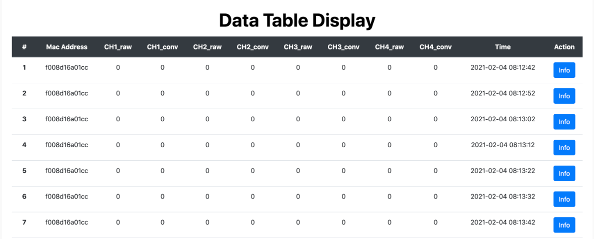
Figure 6-14 : Data Table
Step 5 To see data display of each device, user can click on Info in the row of the device, then the data display will be shown as figure below. And to go back to the data table page, click on Back
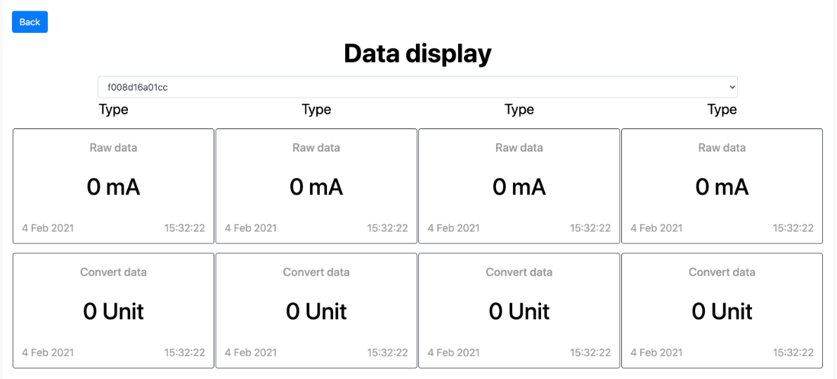
Figure 6-15 : Data Display for testing
Step 6 To finish testing, just click on Finish Test in the data table page. The page will appears as below.

Figure 6-16 : Finish Test page
Note: If user wants to test again, user can click on Click Here to go back to the test.
7 Appendix
7.1 How to setup a Google Sheet as a server to login data
In case the user does not have a personal server, Google Sheets can be used as a server to log the data sent from aMG 4-20 mA to WIFI Data Logger. The process is as follows.
Step 1 Sign in to your google account and open a new google sheet.
Step 2 Insert the following column names to cells 1A-1I.
Step 3 Change the sheet name to test_table (The user can select any name preferred. Make sure there are no space in the sheet name.)
Step 4 Change the spread sheet name to 4-20mA_Google_Server. (The user can use any name preferred. Make sure there are no space in the spread sheet name.)
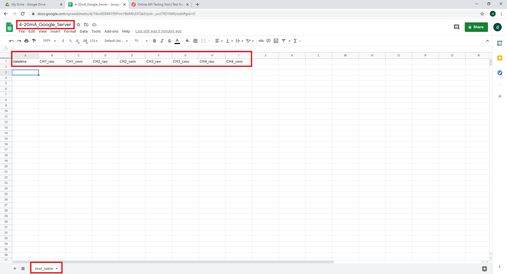
Figure 7-1 : Google Spreadsheet
Step 5 In the Menu Bar go to Tools->Script Editor. This will open up a new tab with an editor to write your Google Script
Step 6 Give the project name as 4-20mA_Google_Script. (The user can use any name preferred. Make sure there are no space in the project name.)
Step 7 Copy and Paste the following code to the editor. Make sure to change the user_sheet variable to that used in Step 3.
// IMPORTANT: Change the sheet name accordingly
var user_sheet = "test_table"

function doGet(e) {
  var ss = SpreadsheetApp.getActive();
  var sheet = ss.getSheetByName(user_sheet);

  var headers = sheet.getRange(1, 1, 1, sheet.getLastColumn()).getValues()[0];
  var lastRow = sheet.getLastRow();

  var cell = sheet.getRange('a1');
  var col = 0;
  var d = new Date();

  for (i in headers){
    val = e.parameter[headers[i]];

    cell.offset(lastRow, col).setValue(val);
    col++;
  }

  return ContentService.createHtmlOutput("Success");
}

function updateSheet(rows) {
  var ss = SpreadsheetApp.getActive();
  var sheet = ss.getSheetByName(user_sheet);
  var column = sheet.getRange(1, 1, 1, sheet.getLastColumn()).getValues()[0];
  for(var i=0;i<rows.length;i++) {
    var d = [];
    for(var j=0;j<column.length;j++) {
      d.push(rows[i][column[j]]);
    }
    sheet.appendRow(d)
  }
}

function doPost(e) {
  let data = JSON.parse(e.postData.contents);
  Logger.log(data);
  updateSheet(data.rows);
  return ContentService.createHtmlOutput("Success");
}
Step 8 In the Menu Bar go to Publish->Deploy as web app...
Step 9 In the pop-up window make sure the correct settings are set and click Deploy.
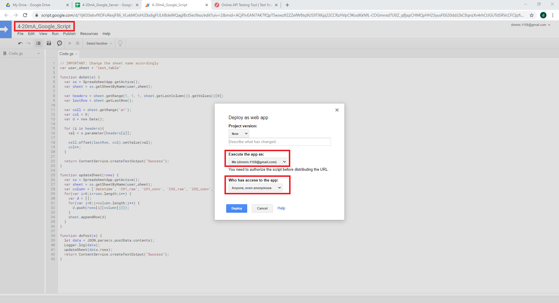
Figure 7-2 : Google Spreadsheet (2)
Step 10 In the pop-up Authorization required, select * Review Permissions*

Figure 7-3 : Google Spreadsheet (3)
Step 11 Next you might be prompted with a new window to sign in to your google account. When you sign-in it will re-direct to a warning page. Here go to Advanced and click Go to 4-20mA_Google_Script (unsafe).
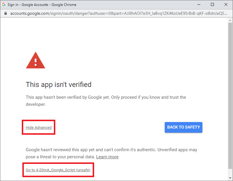
Figure 7-4 : Google Spreadsheet (4)
Step 12 Then click Allow access.
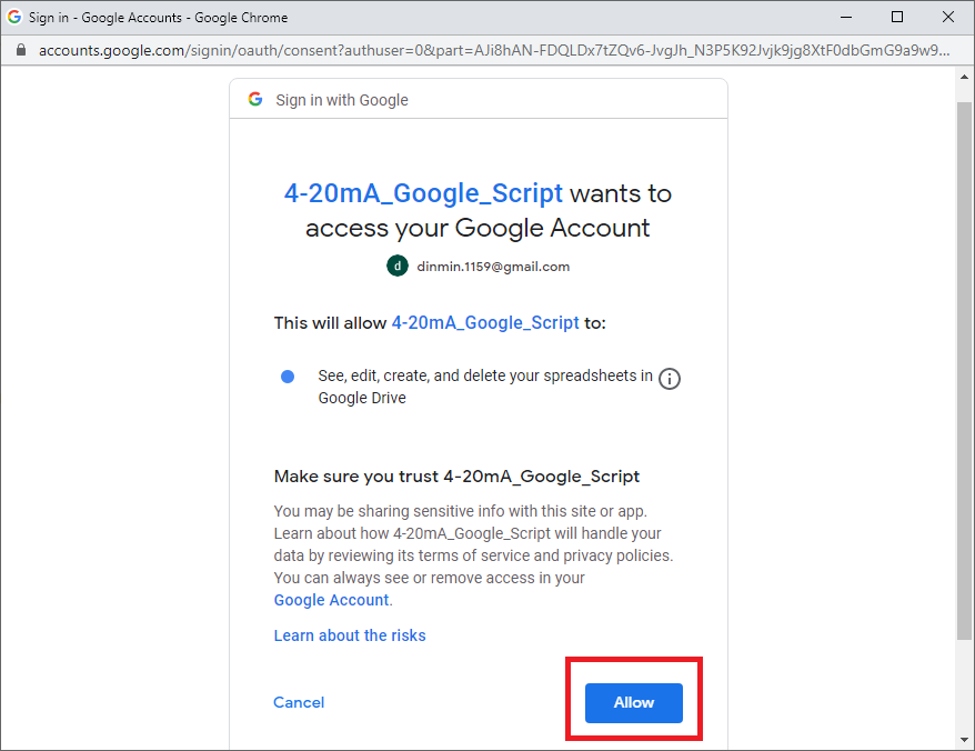
Figure 7-5 : Google Spreadsheet (5)
Step 13 The new window will close and user will be prompted with a pop-up. Copy and Paste the Current web app URL to a known location. This contains the secret key to the Google Sheet you created. Therefore keep this URL safe. Click OK. The URL will look something like this.
https://script.google.com/macros/s/ _{your secret key without curly brackets}_ /exec
Step 14 Now your Google Sheet is a server waiting for GET or POST requests from the client. To test the process simply type the following URL on any browser with a computer connect to internet. This should print some values to the google sheet you created.
https://script.google.com/macros/s/ _{your secret key without curly brackets}_ /exec?id=test_table&datetime=601235&CH1_raw=0&CH1_conv=0&CH2_raw=1&CH2_conv=1&CH3_raw=2&CH3_conv=2&CH4_raw=3&CH4_conv=3
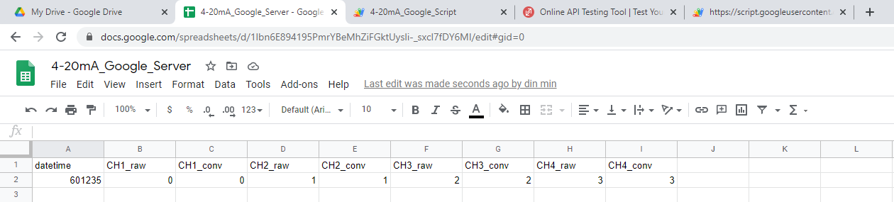
Figure 7-6 : Google Spreadsheet (6)
Step 15 Now power on the aMG 4-20 mA to WIFI Data Logger and sign in during the Configuration Mode
Step 16 Set the System Configuration on setting page by adding the Domain/URL and the Secret Key and Save changes, see System Configuration.
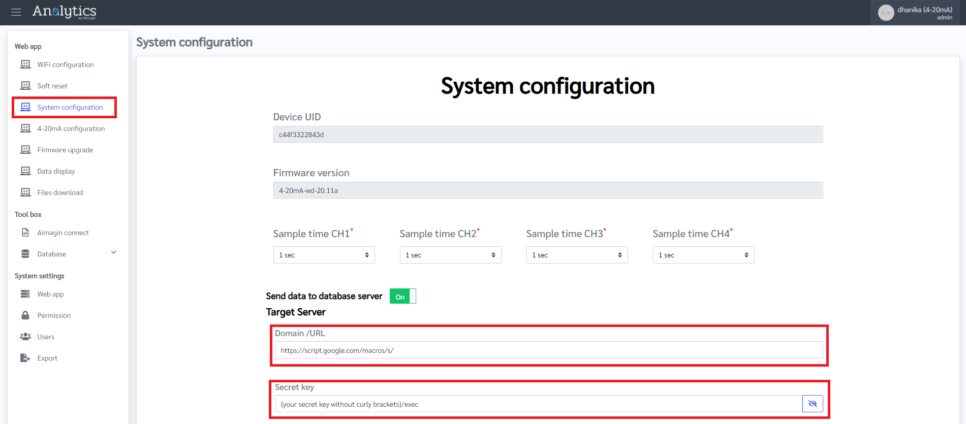
Figure 7-10 : Setting System Configuration
Step 17 Once the device go into running Mode, it will start logging data to the created google sheet.
7.2 Example database server setup with PHP and MySQL database
This is a PHP example for creating a web service to store data submitted from client to MySQL database.
Client posts data to server at URL:
127.0.0.1:8080/[work directory]\
Note: This url is only for local testing. http://l127.0.0.1:8080 should be changed to correct URL.).
The data is in JSON format as shown below:
{
  "id": "esp32",
  "table": "test_table",
  "column": [
    "c1",
    "c2"
  ],
  "rows": [
    {
      "c1": 1,
      "c2": 982
    },
    {
      "c1": 2,
      "c2": 985
    },
    {
      "c1": 3,
      "c2": 988
    }
  ]
}
Where:
id is organization ID;
table is table name;
column is number of data column in any row.
rows is each data to be recorded into the table.
- on Window : https://codebriefly.com/how-to-setup-apache-php-mysql-on-windows-10/
- on Ubuntu : https://www.hostway.co.th/lamp/
- Go to the working directory.
- Start server using command: php -S 127.0.0.1:8080
In index.php:
To receive and decode posted data to query string example:
7.2.1 PHP service for one by one (one hardware to one table)
<?php

# databaseconnect
$servername = "localhost:3306";
$username = "root";
$password = "test1234";
$dbname = "test_db";

$conn = new mysqli($servername, $username, $password, $dbname);
if ($conn->connect_error) {
    die("Connection failed: " . $conn->connect_error);
}

header('Access-Control-Allow-Origin: *');

if ($_SERVER['REQUEST_METHOD'] == "POST") {
    if ($_GET["id"] == "Du81QXQGE6uswzRxXUnagKarauJL80w6/insert") {

        # input json
        $inputJSON = file_get_contents('php://input');
        $data = json_decode($inputJSON, TRUE); //convert JSON into array

        # convert data
        $column = "";
        $values = [];
        $values_string = "";

        $column = implode(", ", $data['column']);

        foreach ($data['rows'] as $row) {
            $r = "";
            foreach ($data['column'] as $i => $col) {
                if ($i + 1 === count($data['column'])) {
                    $r .= '"' .  $row[$col] . '")';
                    array_push($values, $r);
                } else if ($i === 0) {
                    $r .= '("' . $row[$col] . '",';
                } else {
                    $r .= '"' . $row[$col] . '",';
                }
            }
        }

        $values_string = implode(", ", $values);

        # query sql
        $sql = 'INSERT INTO ' . $data['table'] . ' (' . $column . ') VALUES ' . $values_string;
        // print_r($sql);

        # insert to db mysql
        if (count((array)$data['rows'][0]) > 0) {
            if ($conn->query($sql) === TRUE) {
                echo "New record created successfully";
            } else {
                echo "Error: " . $sql . "<br>" . $conn->error;
            }
        }
    }
}

$conn->close();
7.2.2 PHP service for many hardwares in one table
<?php

# databaseconnect
$servername = "localhost:3306";
$username = "root";
$password = "test1234";
$dbname = "test_db";

$conn = new mysqli($servername, $username, $password, $dbname);
if ($conn->connect_error) {
    die("Connection failed: " . $conn->connect_error);
}
//echo 'Connected successfully';

header('Access-Control-Allow-Origin: *');

if ($_SERVER['REQUEST_METHOD'] == "POST") {
    if ($_GET["id"] == "Du81QXQGE6uswzRxXUnagKarauJL80w6/insert") {
        # input json
        $inputJSON = file_get_contents('php://input');
        $data = json_decode($inputJSON, TRUE); //convert JSON into array

        # convert data
        $column = "";
        $values = [];
        $values_string = "";

        $new_str = substr($data['table'], 11);

        array_push($data['column'], "hw_id");

        if (count((array)$data['rows'][0]) > 0) {
            for ($i = 0; $i < count($data['rows']); $i++) {
                $data['rows'][$i]['hw_id'] = $new_str;
            }
        }

        $column = implode(", ", $data['column']);

        foreach ($data['rows'] as $row) {
            $r = "";
            foreach ($data['column'] as $i => $col) {
                if ($i + 1 === count($data['column'])) {
                    $r .= '"' .  $row[$col] . '")';
                    array_push($values, $r);
                } else if ($i === 0) {
                    $r .= '("' . $row[$col] . '",';
                } else {
                    $r .= '"' . $row[$col] . '",';
                }
            }
        }

        $values_string = implode(", ", $values);

        # query sql
        $sql = 'INSERT INTO ' . substr($data['table'], 0, 10) . ' (' . $column . ') VALUES ' . $values_string;

        # insert to db mysql
        if (count((array)$data['rows'][0]) > 0) {
            if ($conn->query($sql) === TRUE) {
                echo "New record created successfully";
            } else {
                echo "Error: " . $sql . "<br>" . $conn->error;
            }
        }
    }
}

$conn->close();
. htaccess for rewrite URL
RewriteEngine On

RewriteBase /esp32_multi
RewriteCond %{REQUEST_FILENAME} !-f
RewriteCond %{REQUEST_FILENAME} !-d
RewriteRule ^(.*)$ index.php?id=$1 [L,QSA]
7.3 Example database server setup with NodeJS and SQLite database
This is NodeJS example for creating a web service to store data submitted from client to SQLite database.
Client posts data to server at URL:
http://localhost:8080/U4tfcUMqnwMxWrGLwNZKdWDMx2XGYfGgb2LzpZJdY6dVdQQ9ReJ377aJEBht6Rkk/insert
Note: This url is only for local testing. http://localhost:8080 shall be replaced to correct URL.
The data is in JSON format as shown below:
{
  "id": "esp32",
  "table": "test_table",
  "column": [
    "c1",
    "c2"
  ],
  "rows": [
    {
      "c1": 1,
      "c2": 982
    },
    {
      "c1": 2,
      "c2": 985
    },
    {
      "c1": 3,
      "c2": 988
    }
  ]
}
id is organization ID
table is table name
column is number of data column in any row.
rows is each data to be recorded into the table
This setup method, NodeJS is required.
To download and install NodeJS, see NodeJS
To run this code:
1. extract web_service.zip
2. install sqlite3 using command: npm install sqlite3
3. start server using command: node server.js
To keep this web service running on server:
1. install pm2 on server using command npm install pm2
2. start the process using command pm2 start server.js
In web_server.zip,
./esp32/db/database.db
./server.js
In case the organization ID is parent folder that contains the SQLite database named database.db . Server.js is nodeJS code for creating web service.
In server.js:
References:const http = require('http'); const url = require('url'); const sqlite3 = require('sqlite3').verbose(); http.createServer(function(req, res){ var qpath = url.parse(req.url, true).pathname; var data = ""; res.setHeader("Access-Control-Allow-Origin", '*'); req.on('data', chunk=> { data += chunk; }).on('end', ()=> { data = JSON.parse(data); if (qpath == '/U4tfcUMqnwMxWrGLwNZKdWDMx2XGYfGgb2LzpZJdY6dVdQQ9ReJ377aJEBht6Rkk/insert') { var params = [], values = []; data.rows.forEach(function(row) { params = params.concat(data.column.map(d=>row[d])); values = values.concat('('+data.column.map(d=>'?')+')'); }); var db = new sqlite3.Database("./"+data.id+"/db/database.db"); db.run(`INSERT INTO ${data.table} (${data.column}) VALUES ${values}`, params, (err)=>{ if(err) { res.write("Failture: "+err.message); } else { res.write("Success"); } res.end(); }); db.close(); } else { res.write(null); res.end(); } }); }).listen(8080);