SMC IOT Terminal Design Case study
Requirements
The SMC IOT Terminal is used to upload the sensor data which is connected to the SMC EX-600 system to the Aimagin smart sensor server as well as to the Aimagin connect local database to visualize the sensor data. The SMC IOT Terminal is based on ESP32 module. In the process, first the SMC IOT Terminal initialize the WiFi in AP mode (Access Point mode) to run the Aimagin Connect server. In this SMC project the Aimagin Connect server on ESP32 is used to configure the settings of IOT terminal using interactive forms and visualize the sensor data with widgets (Numeric displays, Bar charts, Multi-axis graphs and etc). The system remains in the AP mode with Aimagin Connect until the user is inactive for 30 seconds or logout from the Aimagin Connect. Once the configuration is finished and the user is inactive or logout from the Aimagin Connect, the IOT Terminal is switched the WiFi from AP mode to Station mode to upload the sensor data to the Aimagin smart sensor using internet and save those sensor data in the Aimagin Connect local database.
There are five different web pages to configure the SMC IOT Terminal and visualize the sensor data.
- WiFi Configuration page
This page is used to configure the WiFi settings (SSID, Password, IP address and etc.) in Station mode to upload the sensor data to the Aimagin Smart Sensor server. - Target Server page
The usage of Target Server page is to setup the URL of the server which the data is uploaded (in this case: the URL of the Aimagin Smart Sensor server) - Factory Reset page
It is used to reset data which is saved in above two web pages to default. - Analog Input Configuration page
This page is used to convert the analog input sensor readings to required units. Usually the SMC analog input sensor readings shows in mA or in V. But it should be converted to a unit which can easily understand. - SMC Dash Board page
Dash board page shows the sensor reading data with the Aimagin Connect widgets.
Web Page Designing (using Aimagin Connect)
Web page designing in Aimagin Connect is very user friendly and easy to use with dragging and dropping components and can be designed advanced web pages using it with a minimum knowledge on web designing. Developing most of the web pages for SMC on Aimagin Connect can be divided in to two sections.- Designing the web page
- Creating the database table for data representation on web pages
Following documentation demonstrates developing each web page on Aimagin Connect step by step.
Developing WiFi Configuration page
- Creating the database table
Database table is used to save the WiFi configuration data to connect the SMC IOT Terminal(ESP32) to the internet via wifi router to upload the SMC sensor data to the smart sensor server. There are seven user input parameters(SSID, Password, Static or Dynamic selection, IP address, Subnet mask, Gateway and DNS) on this page. For each parameter, there should be a separate column in database table. Creating a new database table in Aimagin Connect is as follows.
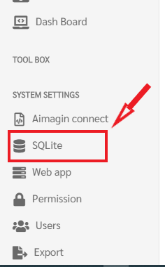
Once login in to the Aimagin Connect server on the web go to SQLite under System settings on the left main menu as in the following figure.
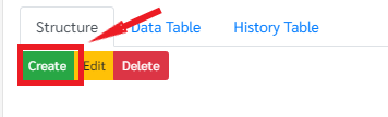
Then click Create on SQLite Page to make a new table
Change the name of the table to wifi_config and click Add to add required columns to the table
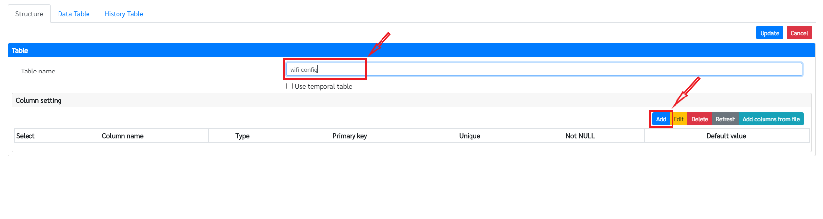
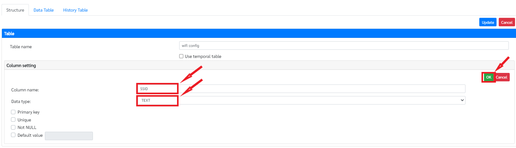
In column setting, add the required Column name and the suitable data type. In this scenario set the column name as SSID and the data type as TEXT. And then click OK to add that column to the table as in the following figure.
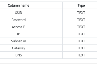
Likewise add the required remaining columns for the wifi_config table as follows and click Update to finalize the table.

- Designing the web page
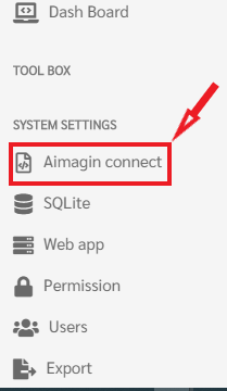
For designing a web page go to Aimagin connect under System Settings as in the following figure
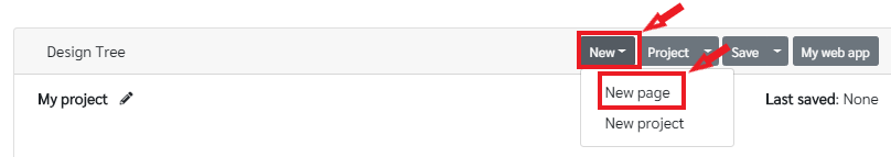
Then click New and select New page on top menu to add a new page to the current project
Change the title of the page under property as in the figure. The title of the page will be displayed on the web browser tab.

The required components and widgets are in the Components section
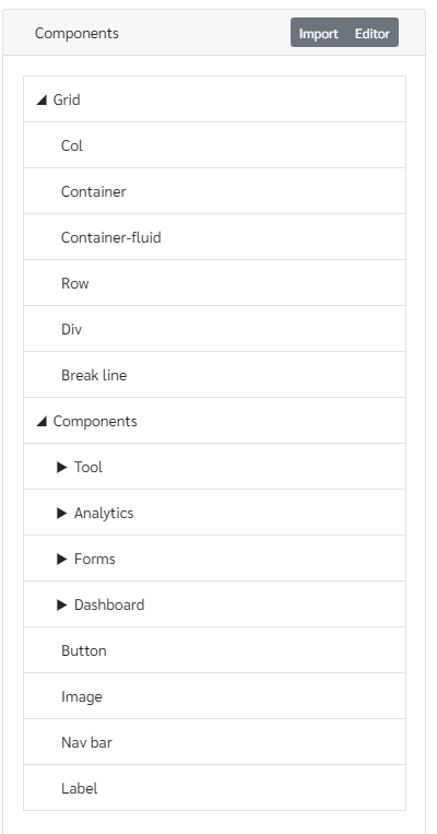
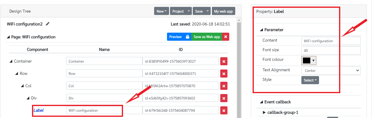
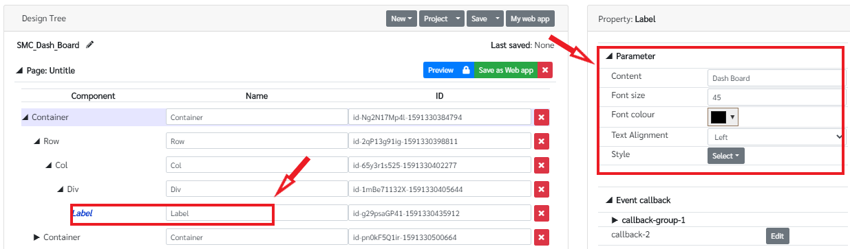
First add a topic to the page. For that drag and drop a container on to the page. The container is under Grid in Components. Then drag and drop a Row on to the Container. If the Row component is dropped on the Container it will make a row inside the Container. Then drag and drop a Col component on the Row component to create a column inside the row. And after that drag and drop a Div component on the Col (column) component. Set the text align as center in Property panel of the Div component to align the text center. Then drop a Label component on the Div component. Click on the added label component and change the Content on Property panel to WiFi Configuration and change the other parameters as required as follows. The component tree will be as in the following figure.
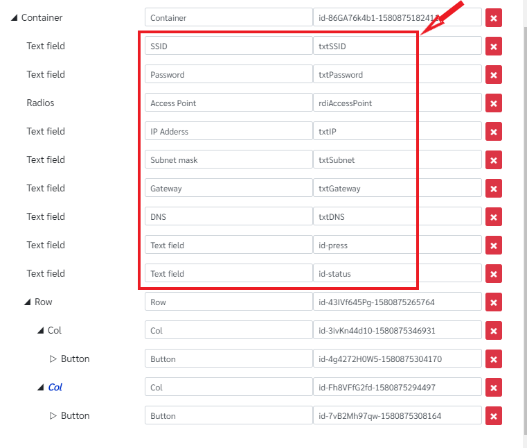
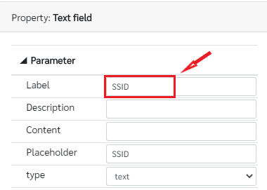
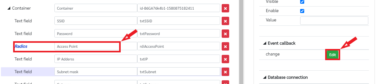
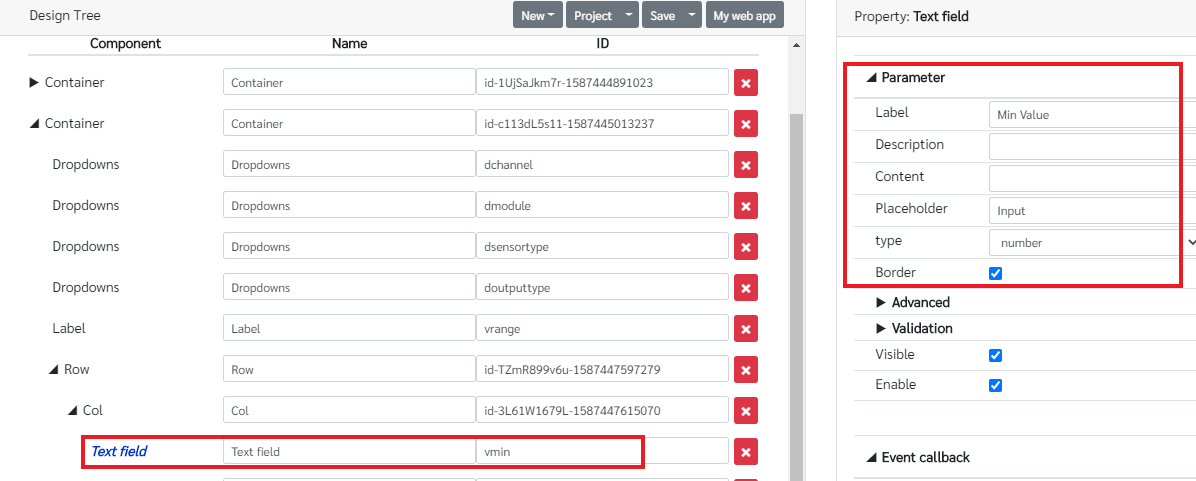
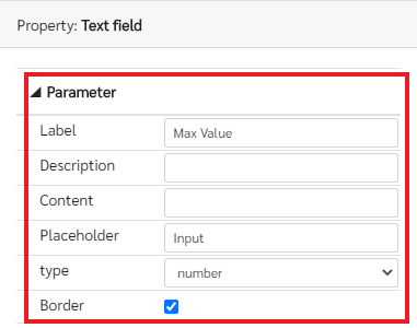
Then add the required text fields, radio buttons and buttons to the WiFi config page. There are six text fields , two radio buttons and two buttons in this page. The six text fields are used to display and let the user to input SSID, Password, IP Address, Subnet Mask, Gateway and DNS. The two radio buttons are used to select the WiFi configuration in Static or Dynamic and the two buttons are used to submit and clear the form data. Before add those components, add a Container component and then add the other components as below. Change the labels and the IDs of the text fields and the radio buttons as in the figure below. The label for text fields can be changed in the Label parameter under the Parameter in text field property pane.
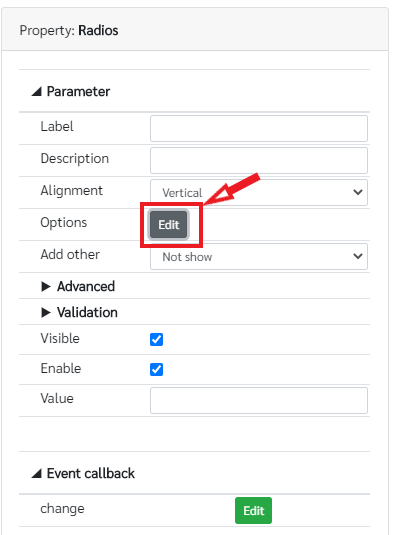
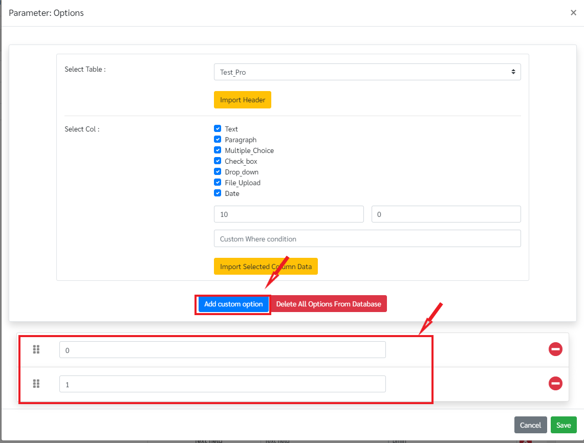
To add the options to the radio button, click on the radio button and go to edit in options under property panel.
Then add two custom options by clicking on Add custom options and name it as Dynamic and Static and save as follows.

Once the web designing is completed the connection between the database table and the web page components should be established. The main feature in this WiFi configuration page, Target Server page and the Analog input configuration page is once the page is loaded it will automatically show the saved data from the database table. And in each page the client checks whether the user alive or not by tracking the key board and the mouse. For that a callback function should be implemented as follow.
First click on the page and click on the edit on init under event callback.

Add the callback function as below. Once the function is implemented click Save.
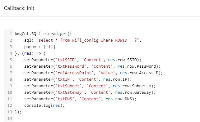
AmgCnt.SQLite.read.get({
    sql: "select * from wifi_config where ROWID = ?",
    params: ['1']
}, (res) => {
    setParameter('txtSSID', 'Content', res.row.SSID);
    setParameter('txtPassword', 'Content', res.row.Password);
    setParameter('rdiAccessPoint', 'Value', res.row.Access_P);
    setParameter('txtIP', 'Content', res.row.IP);
    setParameter('txtSubnet', 'Content', res.row.Subnet_m);
    setParameter('txtGateway', 'Content', res.row.Gateway);
    setParameter('txtDNS', 'Content', res.row.DNS);
    console.log(res);
});

//Check the user alive
let lastEventTime = Date.now();
const max_idle = 30; /*30 seconds*/
let activeStatus = true;

window.addEventListener('mousemove', function(e) {
    lastEventTime = Date.now();
    //console.log(e);
    //setParameter('id-move', 'Content', "(" + e.pageX + ", " + e.pageY + ")");//
    check()
});

window.addEventListener('keydown', function(e) {
    /*or use keyup, keydown*/
    lastEventTime = Date.now();
    console.log(e); /*check e to see other detail such as, ctrl, shift, ...*///
    //setParameter('id-press', 'Content', e.key + " (" + e.keyCode + ")");//
    check()
});

function updateLastEventTime(e) {
    lastEventTime = Date.now();
    //setParameter('id-press', 'Content', "Touch Event");
    check()
}

window.addEventListener('touchstart', updateLastEventTime);
window.addEventListener('touchend', updateLastEventTime);
window.addEventListener('touchcancel', updateLastEventTime);
window.addEventListener('touchmove', updateLastEventTime);

function check() {
    let dt = Math.round((Date.now() - lastEventTime) / 1000);
    if (dt > max_idle) {
        /*no mouse/keyboard events more than 30 seconds*/
        if (activeStatus == true) {
            //setParameter('id-status', 'Content', "Inactive");//c
            activeStatus = false;
            AmgCnt.Esp32.setClientActive(activeStatus);
        }
    }else {//c
        //setParameter('id-status', 'Content', "Active (Idle: " + (max_idle - dt) + " s)");//c
        if (activeStatus == false) {//c
            activeStatus = true;//c
            AmgCnt.Esp32.setClientActive(activeStatus, function(e) {//c
              console.log("server response: "+e.data);//c
            });
        }
    }
}

setInterval(check, 1000);
In this callback function, the web page acquires data of the first row from the wifi_config table using AmgCnt.SQLite.read.get function with the suitable SQL and each column data from the table will be shown in the each web page component with the setParameter function. In this setParameter function the first parameter should be the Name of the component, the second parameter will be the parameter that you are going to change; for the text fields the parameter is the Content. The third parameter is the value; in this case the particular column data from the database table.
In the WiFi configuration the user select Dynamic in radio buttons the IP Adderss, Subnet mask, Gateway and DNS text fields should be disabled. It should enable when the user select Static in wifi configuration. For that a callback function should be implemented when the selection of the radio button is changing. Click on the radios component and click on the edit in the change event under event callback.
The callback funtion should be as follow. It basically disable those text fields if the selection is Dynamic. Otherwise it will enable the text fields.

var v = getParameter('rdiAccessPoint', 'Value');
!setParameter('txtIP', 'Enable', v=="Static");
!setParameter('txtSubnet', 'Enable', v=="Static");
!setParameter('txtGateway', 'Enable', v=="Static");
!setParameter('txtDNS', 'Enable', v=="Static");
Next the callback function for the Update button. For this the data in each text fields and the radio buttons should be inserted to the wifi_config table. Click on the Update button component and go to Edit of the mouseclick event under Event callback as follow.

Add the following functions to the mouseclick event
AmgCnt.SQLite.read.get({
    sql: "select SSID from wifi_config ",
    params: []
}, (res) => {
    if (res.row == undefined) {
        AmgCnt.SQLite.create.run({
            sql: "insert into wifi_config (SSID, Password, Access_P, IP, Subnet_m, Gateway, DNS) values(?, ?, ?, ?, ?, ?, ?)",
            params: [getParameter('txtSSID', 'Content'),getParameter('txtPassword', 'Content'),getParameter('rdiAccessPoint', 'Value'),getParameter('txtIP', 'Content'),getParameter('txtSubnet', 'Content'),getParameter('txtGateway', 'Content'),getParameter('txtDNS', 'Content')]
        }, (res) => {
            alert("Data has been inserted");
        });

    } else {
        AmgCnt.SQLite.update.run({
            sql: "update wifi_config set SSID = ? ,Password = ?, Access_P = ?,IP = ?, Subnet_m = ? ,Gateway = ?, DNS = ? where ROWID = ?",
            params: [getParameter('txtSSID', 'Content'),getParameter('txtPassword', 'Content'),getParameter('rdiAccessPoint', 'Value'),getParameter('txtIP', 'Content'),getParameter('txtSubnet', 'Content'),getParameter('txtGateway', 'Content'),getParameter('txtDNS', 'Content'),'1']
        }, (res) => {
            alert("Data has been updated");
        });
    }

    console.log(res);
});
In this event, the data in all components is gathered and saved in the wifi_config table. First the client checks whether the data is already in the first row in the wifi_config table. If it is not, the data will be inserted to the first row. If the data is already in the first row, it will update the first row with the current data. AmgCnt.SQLite.create.run function is used to insert the data to the table and AmgCnt.SQLite.update.run function is used to update the data with the current data. getParameter function is used to get the user entered data form the web component (from the text field or from radio button).
The last callback function is used to clear the data of the web page using the clear button. For that click on the clear button and go to mouseclick event of that button and add the following function to clear the data on each component (in text fields and radio buttons).
setParameter('txtSSID', 'Content', '');
setParameter('txtPassword', 'Content', '');
setParameter('rdiAccessPoint', 'Value', '');
setParameter('txtIP', 'Content', '');
setParameter('txtSubnet', 'Content', '');
setParameter('txtGateway', 'Content', '');
setParameter('txtDNS', 'Content', '');
Once the web page designing is finished save the project using the save button and preview the designed web page using preview button as in the following figure.

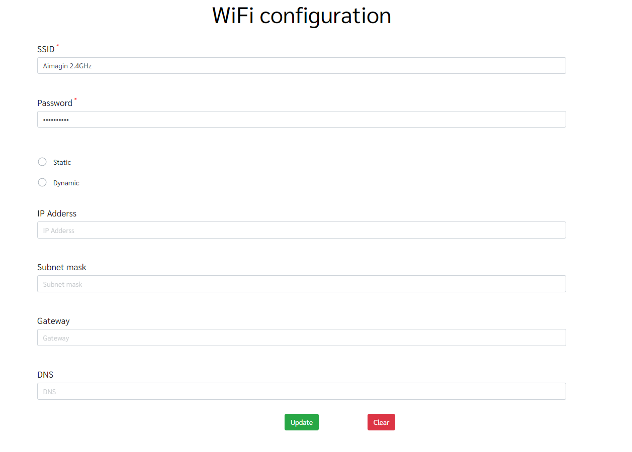
The final web page looks as follow. Try with adding data to the web page and submit those data. Once you load the page again it will show the last submitted data that you entered.
Developing Target Server page
- Creating the database table
Create a new table in SQLite page and name it as target_server. There are two columns in this table; IP and Key. Configure those columns as follow.
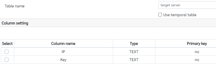
Once the columns are added update the table using Update button
- Designing the web page
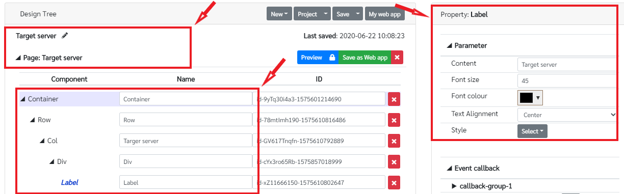
In the Target Server page, there are two text fields to insert the URL of the server and the Key and two buttons to update and clear the data. Go to Aimagin Connect page, add a new web page and name it as in following figure. Then add a topic to the page as in the WiFi configuration page and change the label as Target Server.
Then add the two text fields and two buttons in to the page as in the following figure. Change the id of each text field as required.
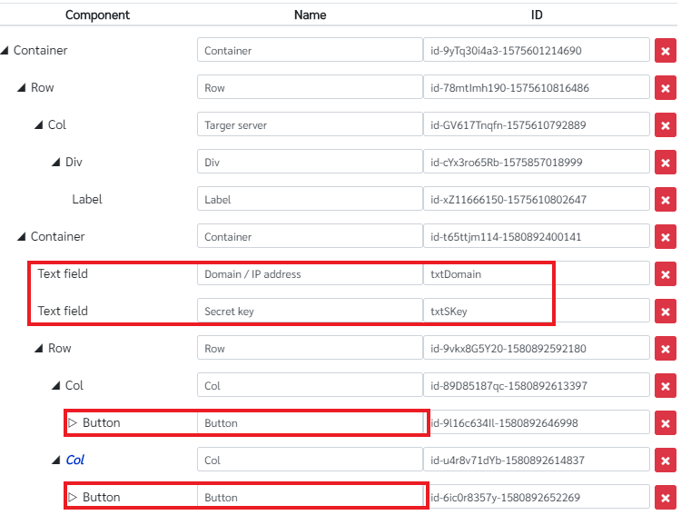
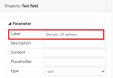
The labels of each text fields as follows. The label content can be changed by clicking on each text field and changing the Label parameter in the Property pane as in the following figures.

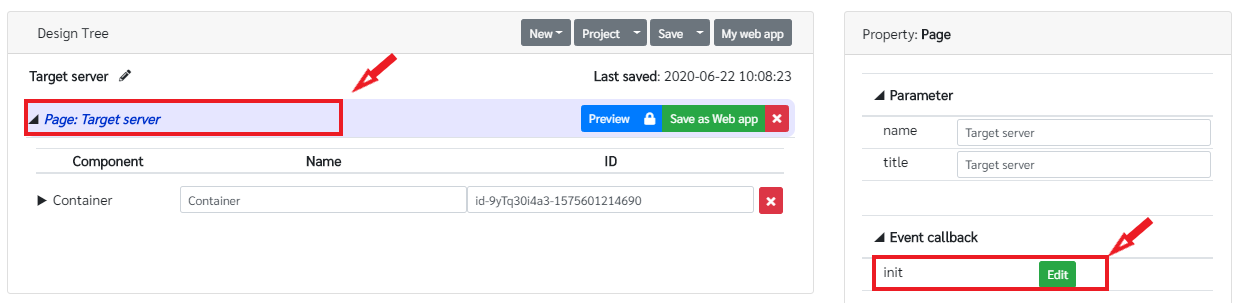
Once all the components for the web page are inserted, the required callback function should be implemented as in the WiFi Configuration page to show the last saved data in the database table once the web page is loaded and to save the latest data in the database table. First implement the functions for displaying the saved data in the database table and check the whether the user is active. For that click the page of the Target Server and edit the init callback under Event callback in the property pane as in the following figure and add the following functions.
AmgCnt.SQLite.read.get({
    sql: "select * from target_server where ROWID = ?",
    params: ['1']
}, (res) => {
    setParameter('txtDomain', 'Content', res.row.IP);
    setParameter('txtSKey', 'Content', res.row.Key);

    console.log(res);
});

//Check the user alive
let lastEventTime = Date.now();
const max_idle = 30; /*30 seconds*/
let activeStatus = true;

window.addEventListener('mousemove', function(e) {
    lastEventTime = Date.now();
    //console.log(e);
    //setParameter('id-move', 'Content', "(" + e.pageX + ", " + e.pageY + ")");
    check()
});

window.addEventListener('keydown', function(e) {
    /*or use keyup, keydown*/
    lastEventTime = Date.now();
    //console.log(e); /*check e to see other detail such as, ctrl, shift, ...*/
    //setParameter('id-press', 'Content', e.key + " (" + e.keyCode + ")");
    check()
});

function updateLastEventTime(e) {
    lastEventTime = Date.now();
    //setParameter('id-press', 'Content', "Touch Event");
    check()
}

window.addEventListener('touchstart', updateLastEventTime);
window.addEventListener('touchend', updateLastEventTime);
window.addEventListener('touchcancel', updateLastEventTime);
window.addEventListener('touchmove', updateLastEventTime);

function check() {
    let dt = Math.round((Date.now() - lastEventTime) / 1000);
    if (dt > max_idle) {
        /*no mouse/keyboard events more than 30 seconds*/
        if (activeStatus == true) {
            //setParameter('id-status', 'Content', "Inactive");
            activeStatus = false;
            AmgCnt.Esp32.setClientActive(activeStatus);
        }
    }
}

setInterval(check, 1000);
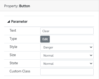
Then implement functions for the Update button and the clear button. The parameter configuration for those buttons as follow.

The required functions for the Update buttons is as follow. Those functions should be added to the mouseclick event under Event callback in the property pane of the Update button to save the web page data in the database table.
AmgCnt.SQLite.read.get({
    sql: "select IP from target_server ",
    params: []
}, (res) => {
    if (res.row == undefined) {
        AmgCnt.SQLite.create.run({
            sql: "insert into target_server (IP, Key) values(?, ?)",
            params: [getParameter('txtDomain', 'Content'),getParameter('txtSKey', 'Content')]
        }, (res) => {
            alert("Data has been inserted");
        });

    } else {
        AmgCnt.SQLite.update.run({
            sql: "update target_server set IP = ? ,Key = ? where ROWID = ?",
            params: [getParameter('txtDomain', 'Content'),getParameter('txtSKey', 'Content'),'1']
        }, (res) => {
            alert("Data has been updated");
        });
    }

    console.log(res);
});
Then the callback functions for the clear button to clear the data on web page. Add the following functions to the mouseclick event under Even callback in the Clear button property pane.
setParameter('txtDomain', 'Content', '');
setParameter('txtSKey', 'Content', '');
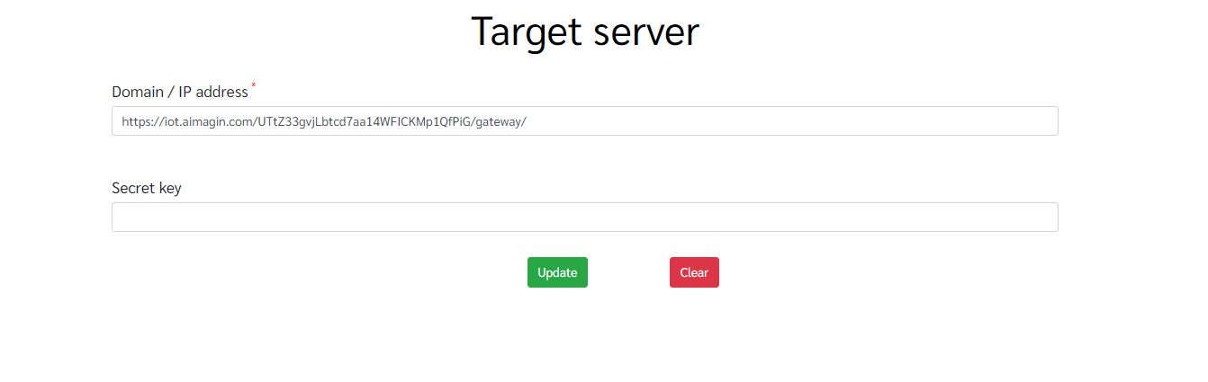
After that save the project using the Save the button on the top menu and preview it using the Preview button. The preview of the page will be as follow. Test with adding data to the text fields and submitting it. Once you reload the page it will show the last submitted data.
Developing Factory Reset page
For this particular page there is no database table. The purpose of this page is to rest to default data in previous database tables.
- Designing the web page
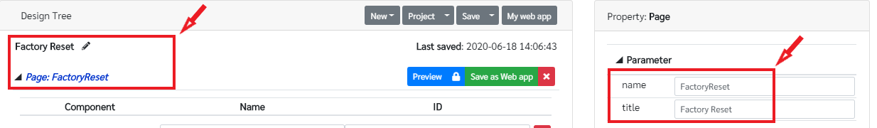
There is only one button on this page. First go to Aimagin Connect page to design the web page. Add a new page change the name of the page as Factory Reset as in following figure.
And then add the title to the page using label component as in the previous pages and change the content of the label to Factory Reset.
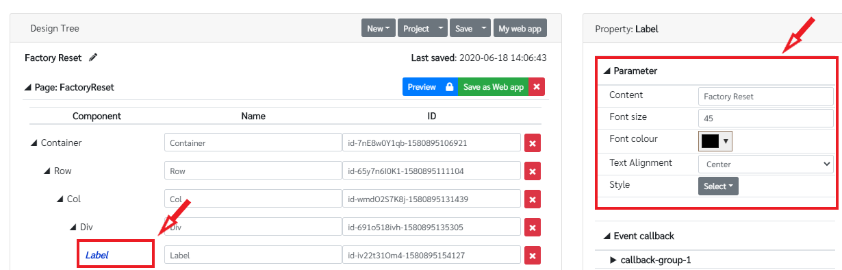
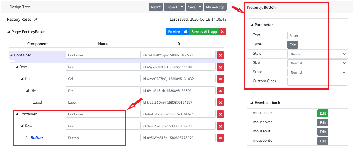
Then add a button to the page to reset as in the following figure and change the parameter configuration of the button as follow.
Next task is to implement callback functions to this page. First add the function to check whether the user is active or not. For that add the following functions to the page init callback by clicking the page and edit the init event under Even callback in Page property pane.
//Check the user alive
let lastEventTime = Date.now();
const max_idle = 30; /*30 seconds*/
let activeStatus = true;

window.addEventListener('mousemove', function(e) {
    lastEventTime = Date.now();
    //console.log(e);
    //setParameter('id-move', 'Content', "(" + e.pageX + ", " + e.pageY + ")");
    check()
});

window.addEventListener('keydown', function(e) {
    /*or use keyup, keydown*/
    lastEventTime = Date.now();
    //console.log(e); /*check e to see other detail such as, ctrl, shift, ...*/
    //setParameter('id-press', 'Content', e.key + " (" + e.keyCode + ")");
    check()
});

function updateLastEventTime(e) {
    lastEventTime = Date.now();

    check()
}

window.addEventListener('touchstart', updateLastEventTime);
window.addEventListener('touchend', updateLastEventTime);
window.addEventListener('touchcancel', updateLastEventTime);
window.addEventListener('touchmove', updateLastEventTime);

function check() {
    let dt = Math.round((Date.now() - lastEventTime) / 1000);
    if (dt > max_idle) {
        /*no mouse/keyboard events more than 30 seconds*/
        if (activeStatus == true) {
            //setParameter('id-status', 'Content', "Inactive");
            activeStatus = false;
            AmgCnt.Esp32.setClientActive(activeStatus);
        }
    }
}

setInterval(check, 1000);
Then add the required function to the Reset button to reset the default values to the wifi_config table and the target_server table. Refer the following functions for the Reset button. Add those functions to the mouseclick event of the button.
var r = confirm("Are you sure?");
 if (r == true) {
     AmgCnt.SQLite.read.get({
         sql: "select IP from target_server ",
         params: []
     }, (res) => {
         if (res.row != undefined) {
             AmgCnt.SQLite.update.run({
                 sql: "update target_server set IP = ? ,Key = ? where ROWID = ?",
                 params: ['https://iot.aimagin.com/UTtZ33gvjLbtcd7aa14WFICKMp1QfPiG/gateway/', '', '1']
             }, (res) => {

             });

         } else
         {
            AmgCnt.SQLite.create.run({
            sql: "insert into target_server (IP, Key) values(?, ?)",
            params: ['https://iot.aimagin.com/UTtZ33gvjLbtcd7aa14WFICKMp1QfPiG/gateway/','']
        }, (res) => {
            alert("Data has been inserted");
        });
         }

         console.log(res);
     });

     AmgCnt.SQLite.read.get({
         sql: "select SSID from wifi_config ",
         params: []
     }, (res) => {
         if (res.row != undefined) {
             AmgCnt.SQLite.update.run({
                 sql: "update wifi_config set SSID = ? ,Password = ?, Access_P = ?,IP = ?, Subnet_m = ? ,Gateway = ?, DNS = ? where ROWID = ?",
                 params: ['Aimagin 2.4GHz', '0862462446', 'Dynamic', '', '', '', '', '1']
             }, (res) => {

             });

         } else {
             AmgCnt.SQLite.create.run({
                 sql: "insert into wifi_config (SSID, Password, Access_P, IP, Subnet_m, Gateway, DNS) values(?, ?, ?, ?, ?, ?, ?)",
                 params: ['Aimagin 2.4GHz', '0862462446', 'Dynamic', '', '', '', '']
             }, (res) => {

             });
         }

         console.log(res);
     });

     alert("Configuration data has been reset");

 }
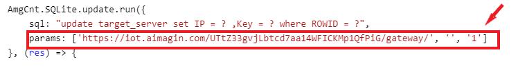
In this reset process once the reset button is clicked the web page asked to confirm the action. Once it confirmed the data will be reset to default. In this case the wifi configuration data is rest to SSID= 'Aimagin 2.4GHz', Password = '0862462446' and mode = 'Dynamic'. For the target server the IP will reset to 'https://iot.aimagin.com/UTtZ33gvjLbtcd7aa14WFICKMp1QfPiG/gateway/'. It can be changed in to any data that you want by changing the parameters in params.
Once the project is saved and previewed, the factory reset page will be as follow.

Developing Analog Input Configuration page
- Creating the database table
Create a new database table and named it as ai_config. Add the required columns to the table. The column configuration of the table is as below.
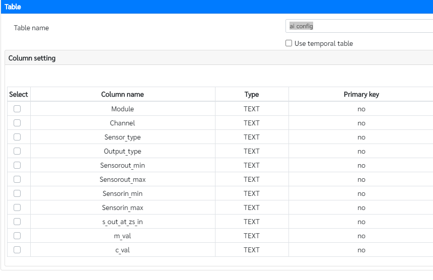
And then click Update to create the table.
- Designing the web page
This web page is used to configure the analog input sensor data. The analog input sensor data from the SMC module is in mA or in V. This page saves the configuration data to convert from mA or V to understandable unit (ex: to pressure in MPa, flow rate in L/min and etc). Since the relationship in between those two unit types are linear, the gradient and the intercept should be calculated to convert from one unit type to other. In this web page those data will be calculated. First go to Aimagin Connect page and add a new page and configure as below.
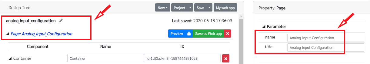
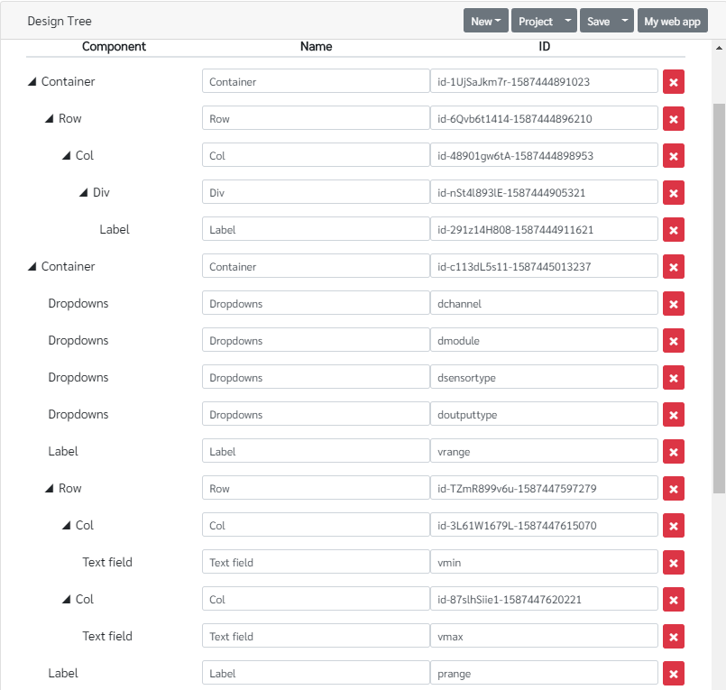
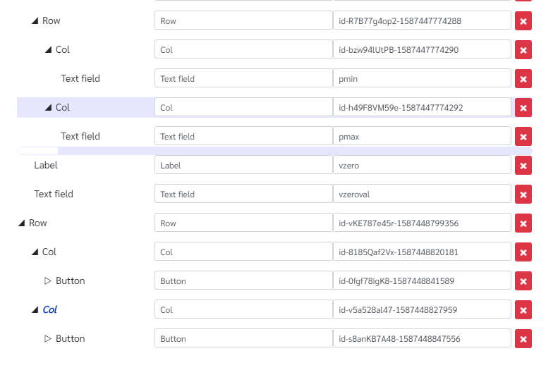
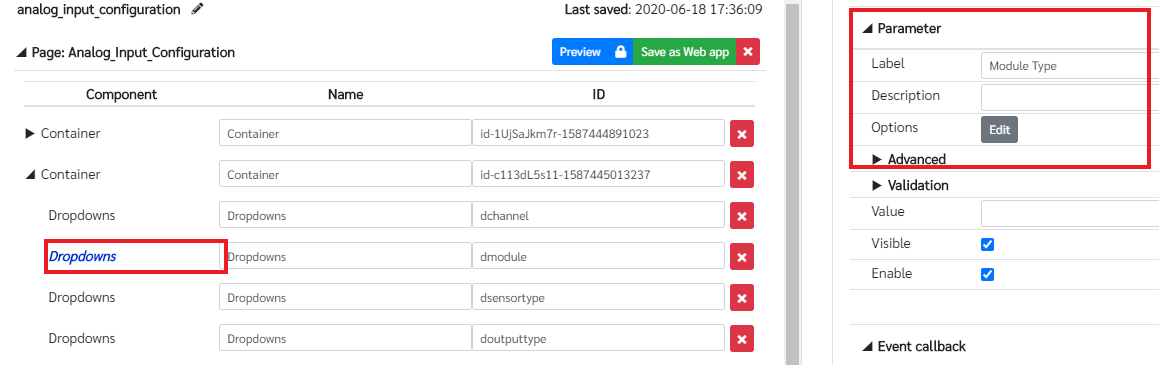
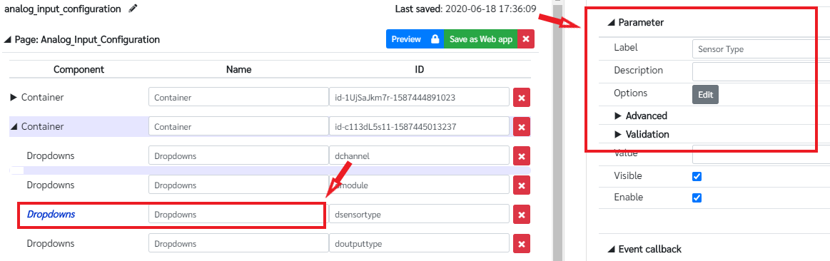
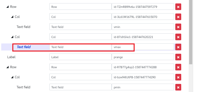
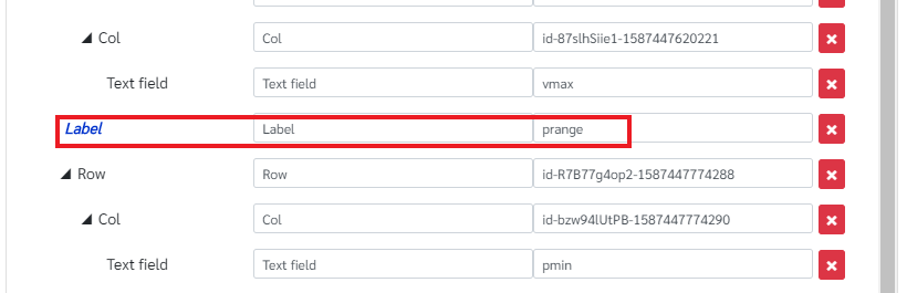
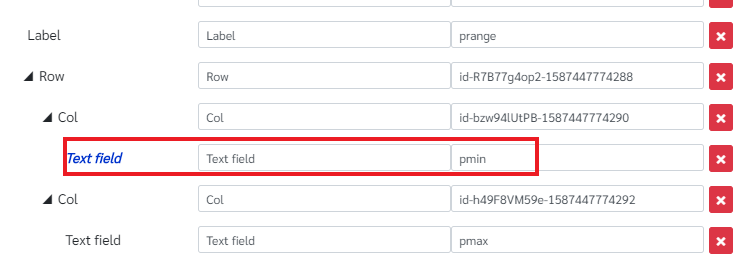
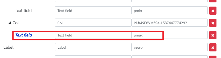
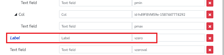
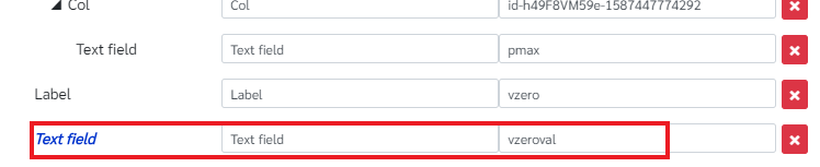
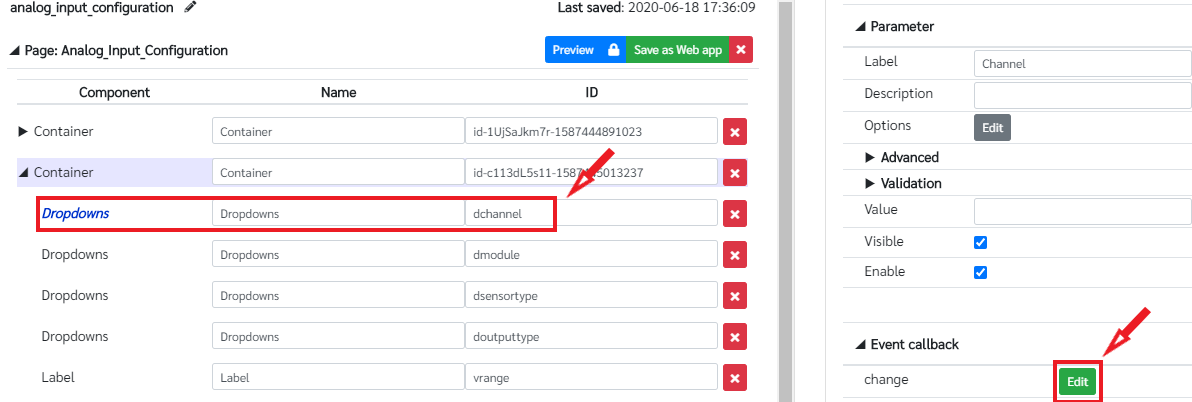
There are four drop down menus to select the sensor channel number, module type to select whether it is a analog input or analog input/output module, sensor type and sensor output type. There are five text fields to save the ranges of the sensor output and sensor input values. And two buttons are added to update and clear data. First add the title for the page using Label component as in previous pages. The design tree of this page is shown in the following figure. Assign the id of the components as in the figure for the drop down menus, text fields and labels.
To add the options to the drop down menus click on that drop down menu component, go to its property pane and edit the options. Set the other parameter of drop down menus as in the figures and save it.
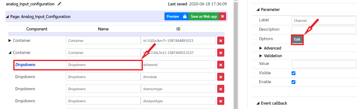
Add the options by clicking on Add Custom options and add two options for channel 0 and channel 1 as in the following figure
Likewise configure the other drop down menus as follows.
The configuration of the drop down menu to select module type as follows.

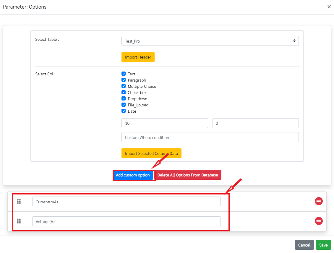
The configuration for the sensor type drop down me is as in the following figures.

The configuration for the last drop down menu which is used to select the output type is in the following figures.

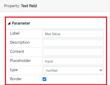
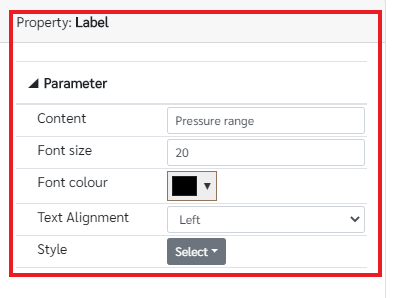
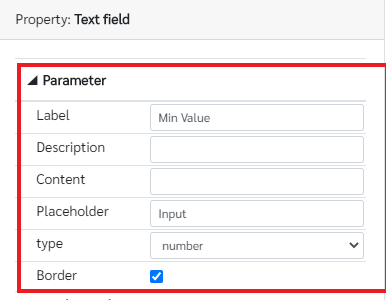
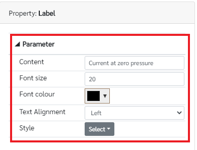
Then the parameter configuration for the labels and the text fields are shown in the following figures.


Next task is to add the callback functions for the required components. The first drop down menu which shows the sensor channel number is used to display the saved data in the ai_config table according to the user selection (with the selection of the channel 0 or 1) and change the content of the labels to the data in the database table. For that add the following functions to the dropdown menu change event. The change event can be edited by clicking on the dchannel drop down menu and going to the change event under Event callback in the drop down property pane.
AmgCnt.SQLite.read.get({
    sql: "select * from ai_config where Channel = ?",
    params: [getParameter('dchannel', 'Value')]
}, (res) => {

    if (res.row != undefined) {
        setParameter('dsensortype', 'Value', res.row.Sensor_type);
          setParameter('dmodule', 'Value', res.row.Module);
        setParameter('doutputtype', 'Value', res.row.Output_type);
        setParameter('vmin', 'Content', res.row.Sensorout_min);
        setParameter('vmax', 'Content', res.row.Sensorout_max);
        setParameter('pmin', 'Content', res.row.Sensorin_min);
        setParameter('pmax', 'Content', res.row.Sensorin_max);
        setParameter('vzeroval', 'Content', res.row.s_out_at_zs_in);

        var sensortype0 = getParameter('dsensortype', 'Value');
        var outtype0 = getParameter('doutputtype', 'Value');

        if (sensortype0 == "Flow Rate(L/min)") {
            setParameter('prange', 'Content', 'Flow rate range');
            if (outtype0 == "Voltage(V)") {
                  setParameter('vrange', 'Content', 'Voltage range');
                setParameter('vzero', 'Content', 'Voltage at zero flow rate');
            } else if (outtype0 == "Current(mA)") {
                  setParameter('vrange', 'Content', 'Current range');
                setParameter('vzero', 'Content', 'Current at zero flow rate');
            }
        } else if (sensortype0 == "Pressure(MPa)") {
            setParameter('prange', 'Content', 'Pressure range');
            if (outtype0 == "Voltage(V)") {
                setParameter('vzero', 'Content', 'Voltage at zero pressure');
                  setParameter('vrange', 'Content', 'Voltage range');
            } else if (outtype0 == "Current(mA)") {
                setParameter('vzero', 'Content', 'Current at zero pressure');
                  setParameter('vrange', 'Content', 'Current range');
            }
        }

    } else {
        setParameter('dmodule', 'Value', '');
           setParameter('dsensortype', 'Value', '');
        setParameter('doutputtype', 'Value', '');
        setParameter('vmin', 'Content', '');
        setParameter('vmax', 'Content', '');
        setParameter('pmin', 'Content', '');
        setParameter('pmax', 'Content', '');
        setParameter('vzeroval', 'Content', '');
    }

    console.log(res);
});
Next callback function is used in the drop down menu which is used to show the sensor type whether it is a flow rate sensor or a pressure sensor. According to the selection, the content of the prange label and vzero label should be changed. For that a callback function is used. Add the following function for the change event of the dsensortype dropdown menu.
var sensortype1 = getParameter('dsensortype','Value');
var outtype1 = getParameter('doutputtype','Value');

if(sensortype1=="Flow Rate(L/min)")
{
  setParameter('prange', 'Content', 'Flow rate range');
  if(outtype1=="Voltage(V)")
  {
    setParameter('vzero', 'Content', 'Voltage at zero flow rate');
  }
  else if(outtype1=="Current(mA)")
  {
    setParameter('vzero', 'Content', 'Current at zero flow rate');
  }
}
else if(sensortype1=="Pressure(MPa)")
{
  setParameter('prange', 'Content', 'Pressure range');
  if(outtype1=="Voltage(V)")
  {
    setParameter('vzero', 'Content', 'Voltage at zero pressure');
  }
  else if(outtype1=="Current(mA)")
  {
    setParameter('vzero', 'Content', 'Current at zero pressure');
  }
}
The next callback function is used in the last drop down menu which shows the data output type whether it is V or mA. According to the selection of the drop down menu the content of the vrange label and vzero label should be changed. The following function should be added to the change event of the doutputtype dropdown menu.
var outtype2 = getParameter('doutputtype','Value');
var sensortype2 = getParameter('dsensortype','Value');

if(outtype2=="Current(mA)")
{
  setParameter('vrange', 'Content', 'Current range');
  if(sensortype2 == "Flow Rate(L/min)")
  {
    setParameter('vzero', 'Content', 'Current at zero flow rate');
  }
  else if(sensortype2=="Pressure(MPa)")
  {
    setParameter('vzero', 'Content', 'Current at zero pressure');
  }
}
else if(outtype2=="Voltage(V)")
{
  setParameter('vrange', 'Content', 'Voltage range');
  if(sensortype2=="Flow Rate(L/min)")
  {
    setParameter('vzero', 'Content', 'Voltage at zero flow rate');
  }
  else if(sensortype2=="Pressure(MPa)")
  {
    setParameter('vzero', 'Content', 'Voltage at zero pressure');
  }
}
Then the callback function for the Submit button should be implemented to calculate the gradient and the intercept and save the data on web page to the database table. For that add the following functions to the mouseclick event of the submit button.
  var s_out_max = getParameter('vmax', 'Content');
var s_out_min = getParameter('vmin', 'Content');
var s_in_max = getParameter('pmax', 'Content');
var s_in_min = getParameter('pmin', 'Content');
let mval = (s_out_max - s_out_min) / (s_in_max - s_in_min);
mval = mval.toFixed(3);

let cval = getParameter('vzeroval', 'Content');

AmgCnt.SQLite.read.get({
    sql: "select Channel from ai_config where Channel = ?",
    params: [getParameter('dchannel', 'Value')]
}, (res) => {
    if (res.row == undefined) {
        if (getParameter('dmodule', 'Value') == '' || getParameter('dsensortype', 'Value') == '' || getParameter('doutputtype', 'Value') == '' || getParameter('vmin', 'Content') == '' || getParameter('vmax', 'Content') == '' || getParameter('pmin', 'Content') == '' || getParameter('pmax', 'Content') == '' || getParameter('vzeroval', 'Content') == '') {
            alert("Fill the required fields");
        } else {
          //setParameter('dmodule', 'Value', res.row.Module);
            AmgCnt.SQLite.create.run({
                sql: "insert into ai_config (Module, Channel, Sensor_type, Output_type, Sensorout_min, Sensorout_max, Sensorin_min, Sensorin_max, s_out_at_zs_in, m_val, c_val) values(?, ?, ?, ?, ?, ?, ?, ?, ?, ?)",
                params: [getParameter('dmodule', 'Value'),getParameter('dchannel', 'Value'), getParameter('dsensortype', 'Value'), getParameter('doutputtype', 'Value'), getParameter('vmin', 'Content'), getParameter('vmax', 'Content'), getParameter('pmin', 'Content'), getParameter('pmax', 'Content'), cval, mval, cval]
            }, (res) => {
                alert("Data has been inserted");
            });
        }

    } else {
        if (getParameter('dmodule', 'Value') == '' || getParameter('dsensortype', 'Value') == '' || getParameter('doutputtype', 'Value') == '' || getParameter('vmin', 'Content') == '' || getParameter('vmax', 'Content') == '' || getParameter('pmin', 'Content') == '' || getParameter('pmax', 'Content') == '' || getParameter('vzeroval', 'Content') == '') {
            alert("Fill the required fields");
        } else {
            AmgCnt.SQLite.update.run({
                sql: "update ai_config set Module = ?, Sensor_type = ?, Output_type = ?,Sensorout_min = ?, Sensorout_max = ? ,Sensorin_min = ?, Sensorin_max = ? ,s_out_at_zs_in = ?, m_val = ?, c_val = ? where Channel = ? ",
                params: [getParameter('dmodule', 'Value'), getParameter('dsensortype', 'Value'), getParameter('doutputtype', 'Value'), getParameter('vmin', 'Content'), getParameter('vmax', 'Content'), getParameter('pmin', 'Content'), getParameter('pmax', 'Content'), cval, mval, cval, getParameter('dchannel', 'Value')]
            }, (res) => {
                alert("Data has been updated");
            });
        }
    }

    console.log(res);
});
For the clear button add the following functions to the mouseclick event to clear the data on the web page
setParameter('dsensortype', 'Value', '');
setParameter('doutputtype', 'Value', '');
setParameter('vmin', 'Content', '');
setParameter('vmax', 'Content', '');
setParameter('pmin', 'Content', '');
setParameter('pmax', 'Content', '');
setParameter('vzeroval', 'Content', '');
setParameter('dchannel', 'Value', '');
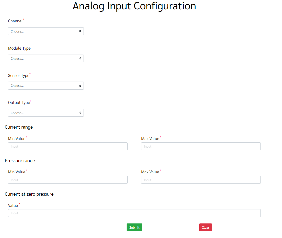
Once the project is saved and previewed it will show as in the following figure.
Developing Dash board page
- Creating the database tables
For this page the database tables fro SMC sensor data are already created. No need to create them again. The tables are named in a format of 'devicexxxxx'. The 5 x are representing a five digit number and it is the UID of each sensor. If the name of the table is starting with device13xxx it is a solenoid, if it starts with device14xxx it is a digital input or digital output and if it starts with device15xxx it is an analog input or analog output.There are specific columns in the SMC sensor data tables to save the data from the sensors. They are listed as follows.
- p1 - Battery level
- p5 - Signal quality
- p16 - Connection Status
- p31 - Soleniod count
- p32 - Soleniod setpoint
- p33 - Soleniod status
- p34 - Soleniod error code
- p35 - Soleniod displacement
- p36 - Soleniod stroke length
- p39 - Digital output count
- p40 - Digital output setpoint
- p41 - Digital output status
- p42 - Digital output error code
- p43 - Digital output displacement
- p44 - Digital output stroke length
- p47 - Analog input current values
- p48 - Analog input physical
- p49 - Analog input setpoint max
- p50 - Analog input setpoint min
- p51 - Analog input error code
- Designing the web page
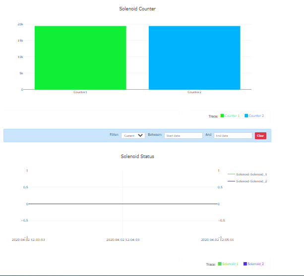
Multi-axis graphs, numeric displays and bar charts are used in this Dash board page to visualize the SMC sensor data. First add the topic to the page as in previous pages and change the content of the label to Dash Board as in the following figure.
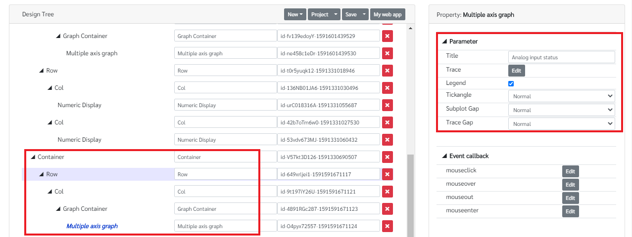
The total design tree of this page is as in the following figure. The widgets are under the Dashboard in the components pane.

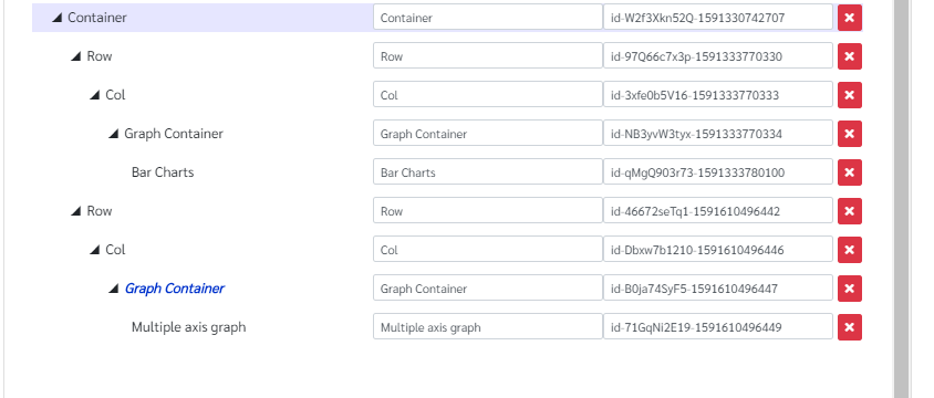
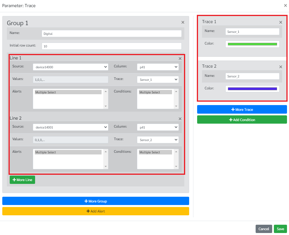
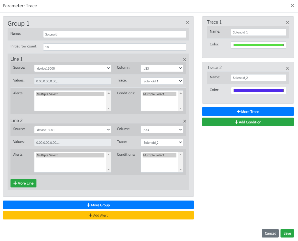
The first widget in this page is a multi axis graph to display the status of the digital input sensors throughout the time. For that follow the following design tree structure to insert a multi axis graph. Then go to Edit in Trace under parameter in the Multi axis graph property pane and configure the other parameters such as setting a title for the graph as in the following figure.
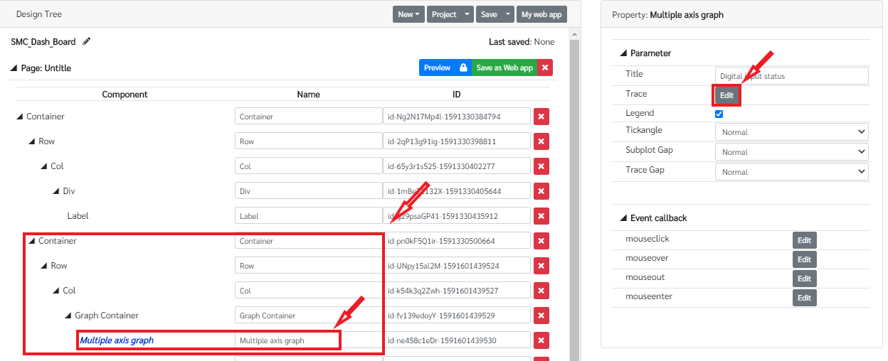
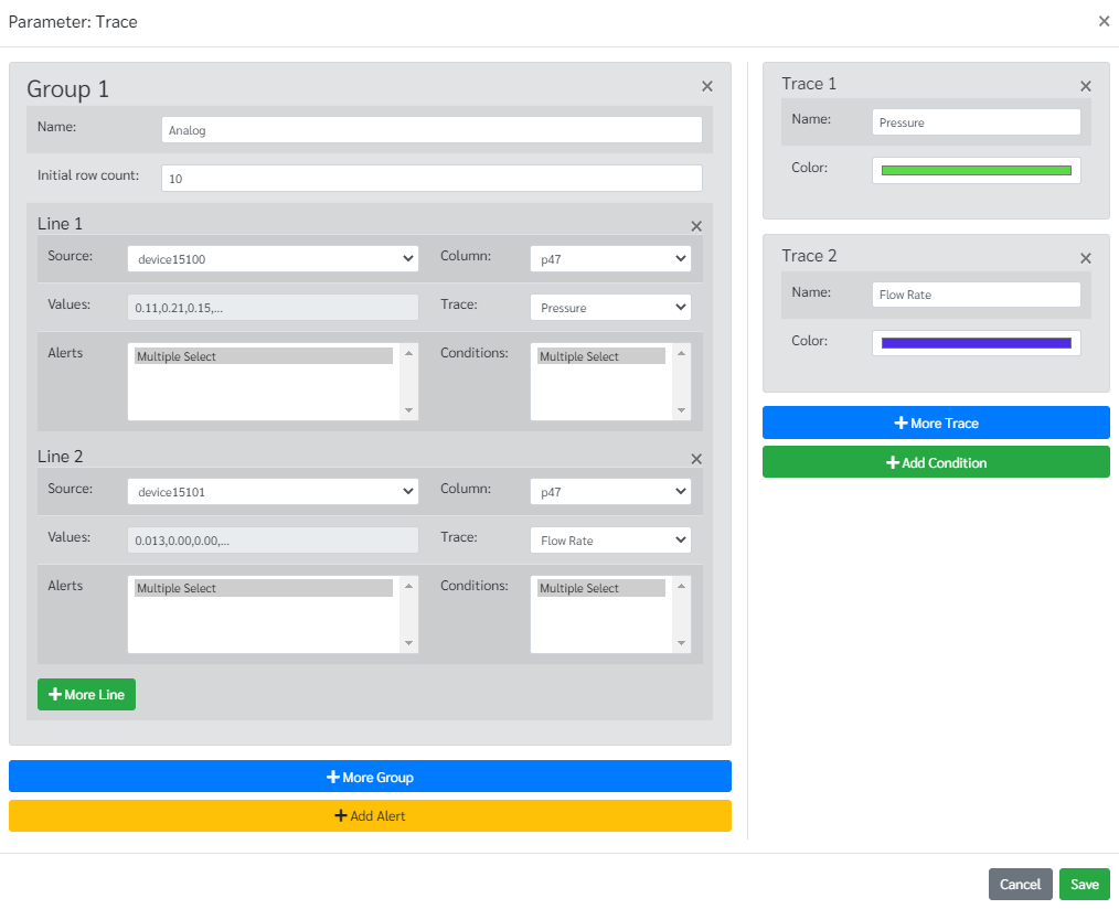
In the trace configuration first add a group by clicking on More group and name it. Then click on More Line to add lines to the graph. Then click on More Trace to add the color to each line. Add the traces as much as you required for the graph. It will depend on the number of lines in the graph. Then go back to the group configuration and set the source of the line by selecting the correct table and the correct column. In this case, this graph shows the status of the digital input sensors in channel 0 and the channel 1 in SMC device. There are two lines in this graph. Use the following graph configuration to setup the graph. Once the configuration is finished save it.
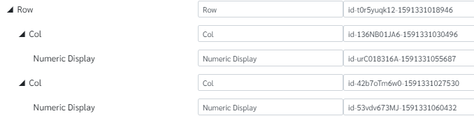
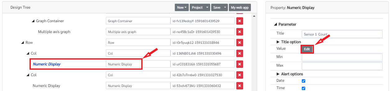
Then there are two Numeric displays to show the counter value of each digital input sensor. For that follow the following design tree structure to add two numeric displays side by side.
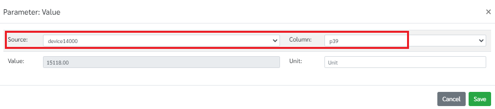
Then go to Edit the Value in Numeric display property pane. Configure each numeric display to display the correct value from the database. For that follow the configuration for both numerical displays as below.
For the first Numeric display
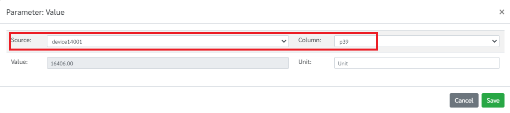
For the second numeric display

Next a multi axis graph is used to show the status of the analog input sensors. The design tree for this graph is in the following figure.
As in the previous multi axis graph go to edit trace to configure the graph . The configuration for the graph is as below.
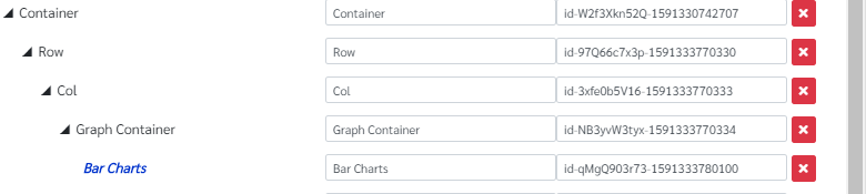
Then there a bar chart is used to represent the counter value of the solenoids. For that follow the design tree structure in the figure. The parameter configuration of the bar chart is as follows
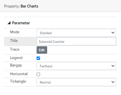
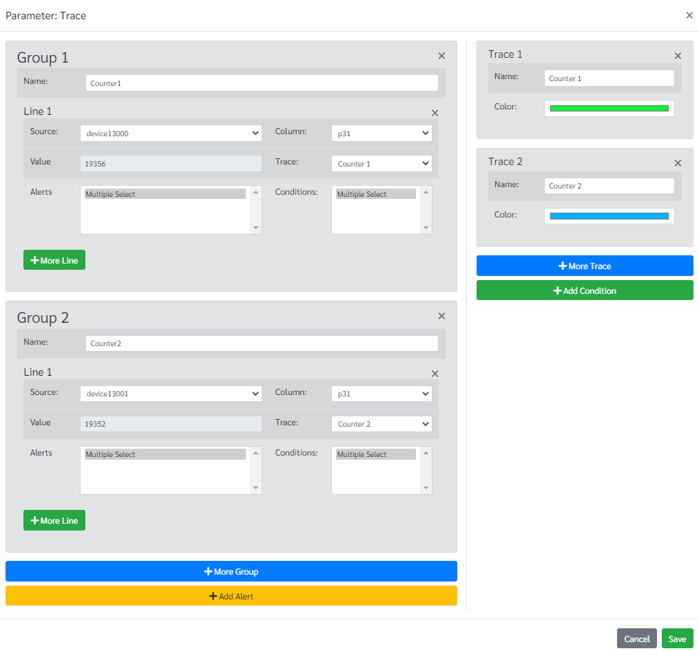
Then go to edit Trace to configure the bar chart. And configure as follow to get the data from the correct table column.
The last widget of this page is a multi axis graph which shows the status of the solenoids. The design tree for that graph is as previous multi axis graphs. It is in the following figure.

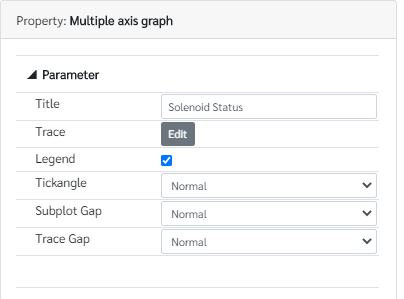
The configuration for this graph is as below to get the data from the corresponding column in the database table.
Once the configuration is finish, save the configuration, the project and then preview the using the Preview button. The web page should look like as below.