Forums » Req. WJ2(ESP32) support »
 PWM LED Control issue
Added by martin van beek over 5 years ago
When trying to control the duty cycle of two channels, with a timestep of 1ms, the duty cycle sweeps from 0 to 100% in approx. 20 seconds instead of the intended 1 second.
Channel0 is incrementing from 0 to 100% and Channel1 is simultaneous decrementing from 100 down to 0%.
The channels are 180 degrees swifted, by setting the hpoint at 0 and 512 respectively.
When observing the debug serial channel, you will find out that there are errors reported for Channel0 and Channel1, "LEDC FADE TOO FAST".
How to solve this problem?
Thanks for your quick response, best regards,
Martin.
Replies (17)
RE: PWM LED Control issue
-
Added by Dhanika Mahipala (ดานิก้า) over 5 years ago
Hi Martin,
I'm not sure whether I understood your question. Please try esp32_pwm.slx model file and let me know whether this is what you are trying to achieve. If so I would provide any clarification regarding the model if necessary.
Please see that there is a minor bug related to ledc block in the current release (Release waijung2_20.11b). Before testing out the above model please replace the following patch file, esp32_ledc.tlc at the location:
" [ your path to waijung2 installation directory ]\waijung2_20.11b\waijung2\targets\esp32\src\blocks "
Regards,
Dhanika
| esp32_ledc.tlc | esp32_ledc.tlc | 8.07 KB | |||
| esp32_pwm.slx | esp32_pwm.slx | 28.5 KB |
RE: PWM LED Control issue
-
Added by martin van beek over 5 years ago
Hi Dhanika,
Thanks for your reply.
The problem with the PWM LEDC block is the "sweep time" from 0 ... 100 percent duty cycle.
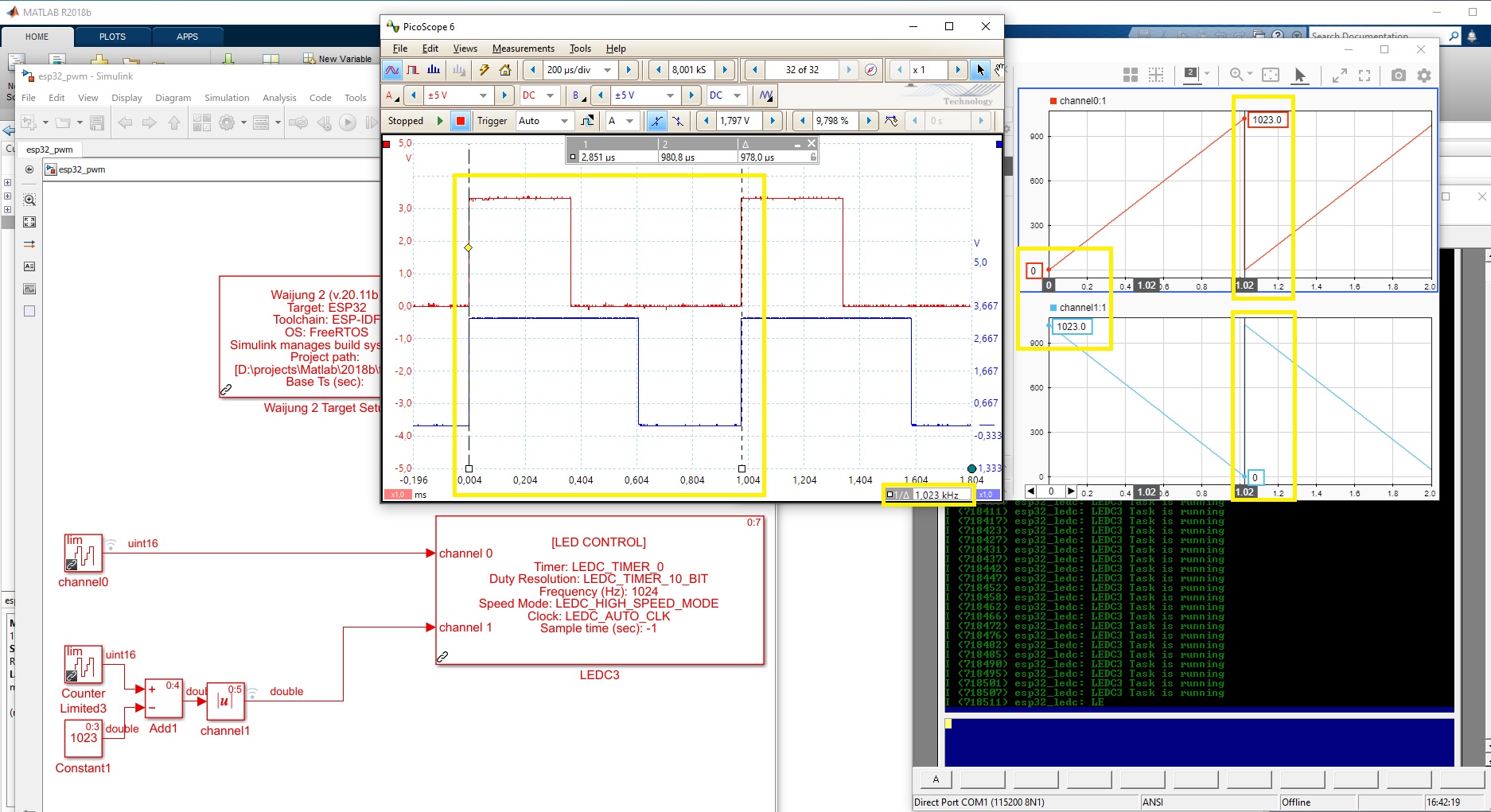
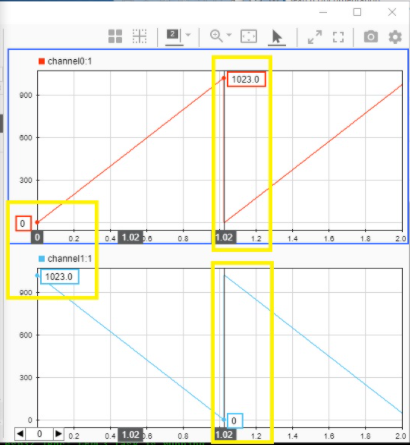
When running the model at a 1 millisecond stepsize, the limited 10bit counter will overrun each 1,024 second as you can see when simulate the complete model.
See the details in the picture attached, "PWM_1ms_step_problem_02.jpg".
In practice, measuring the duty cycle with an oscilloscope, the sweep time is 5,12 seconds !!!
How is it possible that the Matlab simulation differs from the real hardware timing, the real timing is 5 times too slow?
Best regards,
Martin.
RE: PWM LED Control issue
-
Added by martin van beek over 5 years ago
Hi Dhanika,
Do you have any suggestions how to solve this duty cycle "sweep time"?
Thanks for your quick response, kind regards,
Martin.
RE: PWM LED Control issue
-
Added by Dhanika Mahipala (ดานิก้า) over 5 years ago
Hi Martin,
Please bare with me for my next few questions as I try to understand your issue.
When running the model at a 1 millisecond step size, the limited 10bit counter will overrun each 1,024 second as you can see when simulate the complete model.
I believe this is what you are referring to as the simulation results, isn't it? If I understood your question I believe this is exactly what you want to achieve. To reach duty from 0% to 100% in 1024 milliseconds.
In practice, measuring the duty cycle with an oscilloscope, the sweep time is 5,12 seconds !!!
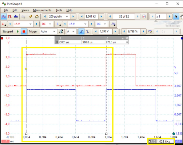
I believe this is what you are referring to as the oscilloscope output, isn't it? Could you please show where you got 5120 milliseconds as sweep time?
Regards,
Dhanika
RE: PWM LED Control issue
-
Added by martin van beek over 5 years ago
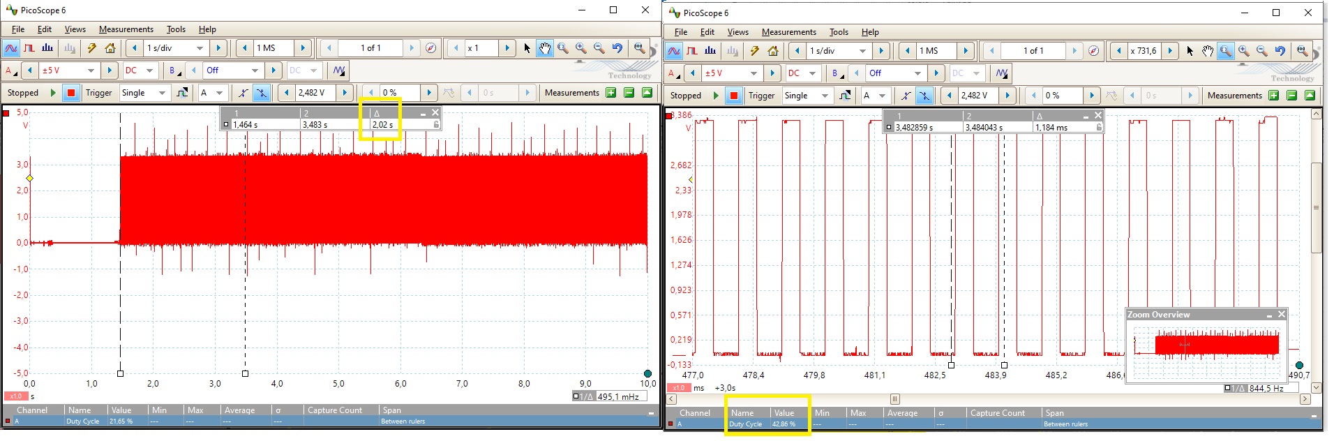
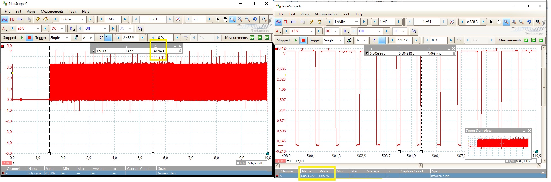
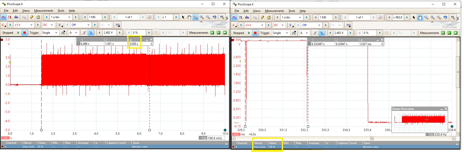
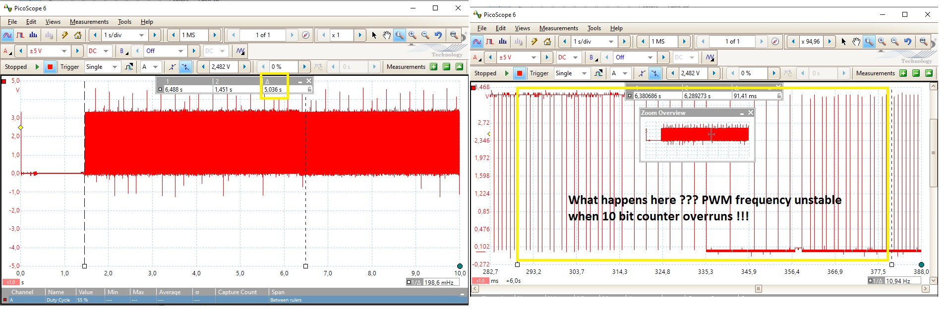
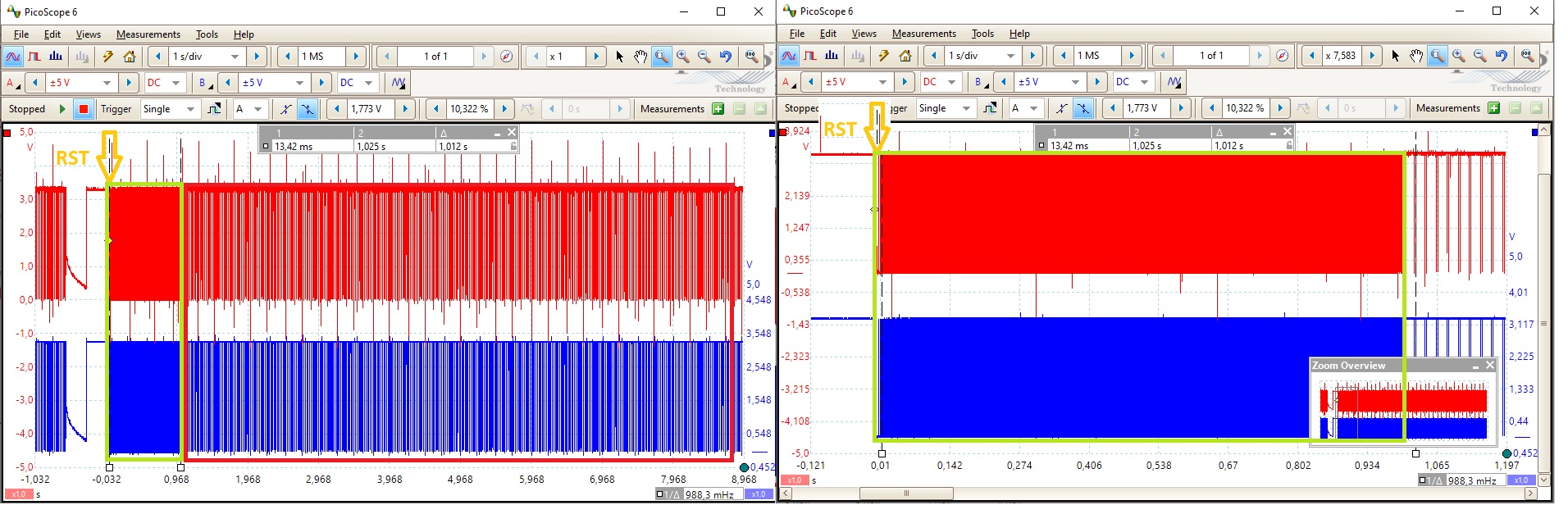
Hi Dhanika,
Herewith the promised timing pictures, grabbed with a real oscilloscope.
You can see that the duty cycle is increasing approx. 20 percent each second, after 5 seconds the pwm sweep is complete. But the intended Matlab model should sweep from 0 to 100 percent within 1,024 second.
This is also the outcome of the Matlab simulation, when running the complete model at 1 millisecond time step.
There is also a strange behavior after 5 seconds, you can see that the 1kHz PWM frequency is slowing down for some cycles. Is this because you reinitiate the PWM counter after each counter overrun?
See for the details the attached pictures.
Kind regards,
Martin.


RE: PWM LED Control issue
-
Added by Dhanika Mahipala (ดานิก้า) over 5 years ago
Hello Martin,
Please check esp32_pwm.slx model file. With this model pin 18 and 19 should sweep from 0 to 100 percent within 1023 milliseconds.
Please let me know the result.
Regards,
Dhanika
| esp32_pwm.slx | esp32_pwm.slx | 32.1 KB |
RE: PWM LED Control issue
-
Added by martin van beek over 5 years ago
Hi Dhanika,
Your new model isn't working in the 'software mode', I want control over the duty cycle and the sweep time.
But your provided 'hardware mode' model sweeps only once, after 1024 ms the output pin of the PWM is most of the time 'true' and 'false' at random intervals.
See for the details the pictures attached.
Can you explain why the pwm in software control mode is 5 times slower than the Matlab simulation, and why the pwm in hardware control mode is sweeping only once.
Thanks for your quick response.
Regards,
Martin.

RE: PWM LED Control issue
-
Added by Dhanika Mahipala (ดานิก้า) over 5 years ago
Hi martin,
You can edit the duty and the sweep time in hardware mode as well. 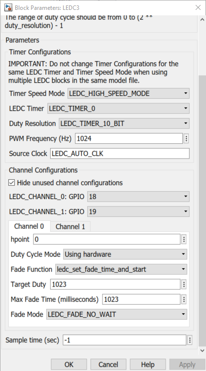
In the mask above you can change the Target Duty and Max Fade Time (milliseconds) parameters to have control over the said tasks. Target Duty is the destination duty and the Max Fade Time is the sweep time in milliseconds.
The model file I sent you was just to clarify whether sweep time of 1023 milliseconds can be achieved. It seems you cannot achieve such frequent transitions in the software mode. I'd verify this first and let you know. The model file I sent you as you probably figured out by now was intended to sweep to 100% and stay there until RESET. Check this esp32_pwm.slx modified model file. This would sweep from 0-100% in 1023 milliseconds and sweep from 100-0% back in 1023 milliseconds.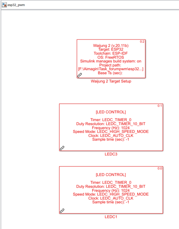
That being said with your feedback I've identified some modifications for the LEDC PWM block to make it more user friendly and less error prone. Please wait for the nest Waijung2 release for these changes to take effect.
Regards,
Dhanika
RE: PWM LED Control issue
-
Added by martin van beek over 5 years ago
Hi Dhanika,
Thanks for your reply with additional information.
My initial intention was to play around with the PWM control block, to control small 'servo motors' for example.
I found out that the 'hardware mode' only accept static property settings like the frequency, duty cycle and the sweeptime.
But when controlling 'servo motors' you need to change the duty cycle on-the-fly.
Changing the duty cycle on-the-fly is only possible in the 'software mode', this mode provides an external 'duty cycle' input pin ( it should be great when there is also an external 'frequency' input pin).
For now I'm curious why the pwm in 'software mode' doesn't match the Matlab simulation/calculation and will need 5 times more time to sweep from 0 ... 100 percent.
Please let me know when you found the root cause of this behavior.
Kind regards,
Martin.
RE: PWM LED Control issue
-
Added by martin van beek over 5 years ago
Hi Dhanika,
Has this PWM issue still your attention?
When is the next release of the Waijung 2 planned, and do you've some information of the Waijung 2 roadmap that you can share.
Look forward to your answers, kind regards,
Martin.
RE: PWM LED Control issue
-
Added by Dhanika Mahipala (ดานิก้า) over 5 years ago
Hi Martin,
Yes, I will be looking into this problem soon.
When is the next release of the Waijung 2 planned, and do you've some information of the Waijung 2 roadmap that you can share.
The next release of waijung2 is still under progress without a release date. Please stay tuned for updates.
Regards,
Dhanika
RE: PWM LED Control issue
-
Added by Dhanika Mahipala (ดานิก้า) over 5 years ago
Hi Martin,
I was able to find the root cause of the problem. It was a bug in the LEDC block. I've fixed it. Here is a simple model file which I used to test it. This esp32_ledc_testw20_11b.slx model file sweep the PWM duty from 0-100% continuously.
Before testing out the above model please replace the following patch file, esp32_ledc.tlc at the location:
" [ your path to waijung2 installation directory ]\waijung2_20.11b\waijung2\targets\esp32\src\blocks "
Regards,
Dhanika
RE: PWM LED Control issue
-
Added by martin van beek over 5 years ago
Hi Dhanika,
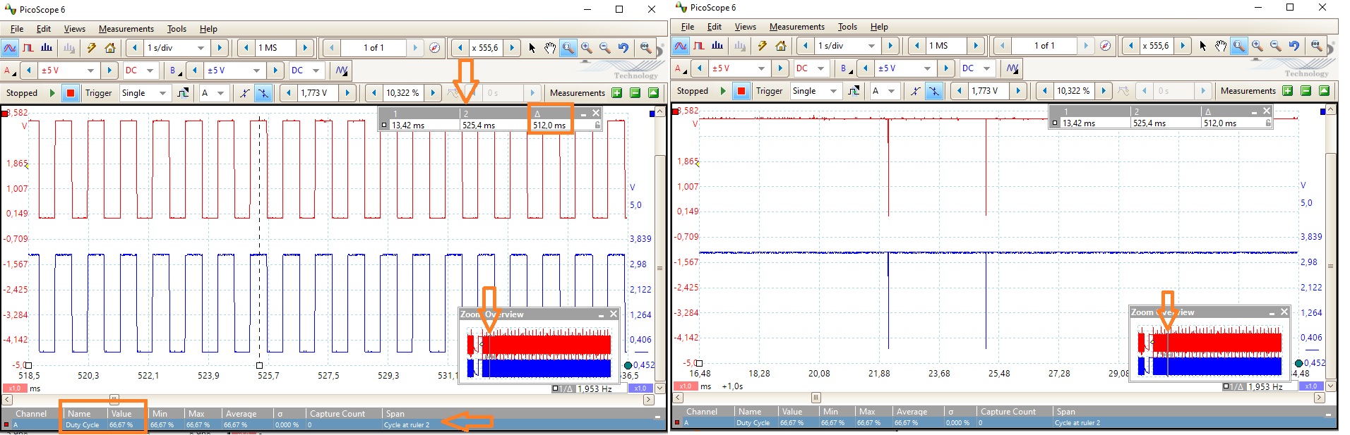
Thanks for your investigation, but by only removing the function call of the ' ESP logging library ', didn't solve that PWM sweep time issue.
The sweep time is reduced from 5 seconds down to 2.5 seconds, and doesn't match the outcome of the Simulink simulation run.
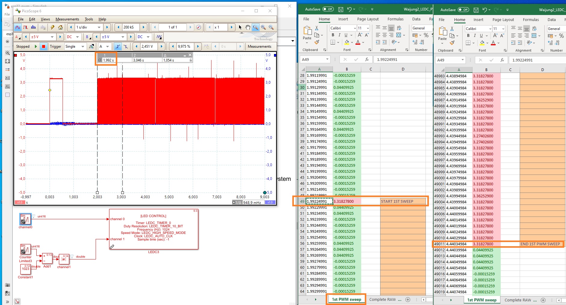
I've attached an Excel file, that contains the real data captured by the hardware oscilloscope, there you can see that the 1st PWM sweep starts at 1.99224991 and ends at 4.44034984 seconds.
Also the PWM base frequency isn't stable and fluctuate quite a lot when we reaching the end of the sweep cycle (duty cycle almost 100 percent). Could this happen because of re-initiating the timer for the next sweep cycle?
Hopefully this information will help you to find the real root cause.
Regards,
Martin.
RE: PWM LED Control issue
-
Added by Dhanika Mahipala (ดานิก้า) over 5 years ago
Background
To change the duty during run time (Software Mode in the LEDC block) ESP LEDC Driver has two APIs. The thread safe API is to use the ledc_set_duty_and_update() function while the non-thread-safe way is to use ledc_set_duty() followed by ledc_update_duty() functions.
In the current LEDC block (waijung2_20.11b) I've used the thread-safe API as a precaution.
Tests using plain c code
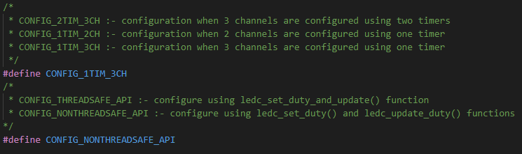
To solve this issue I first prepared a plain C code (ledc_test.c) which could be compiled and upload using the IDF without the need of Waijung2 or Matlab Simulink. In this code by changing the #define (ccode_change_config.PNG) it can be configured for the following instances,
- PWM signal is generated on 3 channels using 2 timers
- PWM signal is generated on 2 channels using 1 timer
- PWM signal is generated on 3 channels using 1 timer
- PWM signal is generated using thread-safe API
- PWM signal is generated using non-thread-safe API
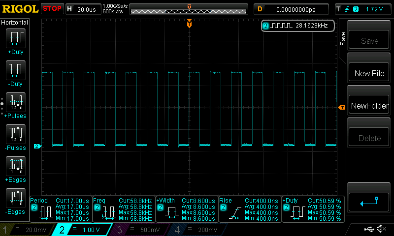
The goal of this program was to find the execution time of the said APIs. To achieve this GPIO PIN 5 was toggled every step cycle. Then GPIOPIN 5 was connected to an oscilloscope for observation. With this setup by measuring time difference between a rising edge and the falling edge that follows, the cycle time can be found. Next the following tests were carried out.
Tests
Test 01: 3 channels using 2 timers - using thread-safe API
Width = 2.92ms
timer per single execution of the API = 2.92ms/3 channels = 0.97ms ~= 1ms
Test 02: 3 channels using 2 timers - using non-thread-safe API
Width = 12microseconds
timer per single execution of the API = 12microseconds/3 channels = 4microseconds
Test 03: 3 channels using 1 timer - using thread-safe API

Width = 2.9ms
timer per single execution of the API = 2.9ms/3 channels = 0.97ms ~= 1ms
Test 04: 3 channels using 1 timer - using non-thread-safe API
Width = 12microseconds
timer per single execution of the API = 12microseconds/3 channels = 4microseconds
Test 05: 2 channels using 1 timer - using thread-safe API

Width = 1.92ms
timer per single execution of the API = 1.92ms/2 channels = 0.96ms ~= 1ms
Test 06: 2 channels using 1 timer - using non-thread-safe API
Width = 8.6microseconds
timer per single execution of the API = 8.6microseconds/2 channels = 4.3microseconds
Conclusion
As you can see the use of thread-safe API (which was used in the LEDC block) causes a blocking process. Therefore when this API is used the LEDC block cannot have a sample time of 1 ms.
Tests using the LEDC block
I tested this theory using the current LEDC block (waijung2_20.11b) by changing the currently used thread-safe API to non-thread-safe API and it solves the problem. However there are some other minor bugs in the current version of the block. Also with the customer feedback we decided to divide the current LEDC block into two separate blocks allowing the user to select different APIs available for the driver and make it less error prone.
For your reference I've done the following tests with the new LEDC blocks. Please wait for the next release to test these out using esp32_ledc_new.slx model file.
Tests
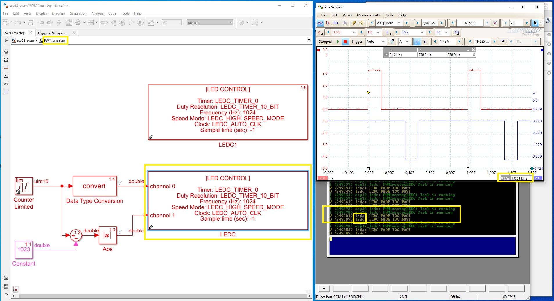
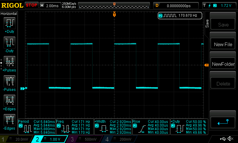
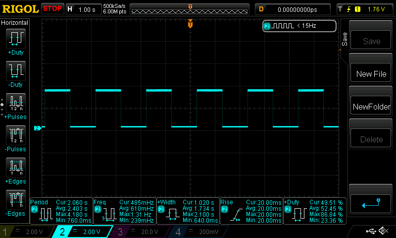
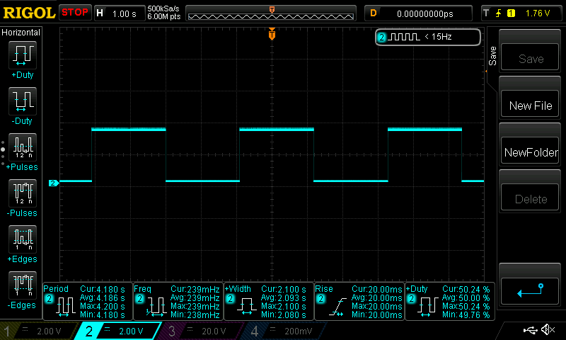
In this model file I've recreated the situation where the problem was identified by you. The duty is set to increment from 0-1023, go back to 0 and continue the process every 1ms. Since the resolution of the timer is set to 10 Bits it should take approximately 1023ms for a single sweep. To measure the sweep time I've toggled GPIO PIN 5 when duty is 0 and 1023. The said GPIO pin was then connected to an oscilloscope for observation. As a result the sweep time can be estimated by measuring the time difference between a rising edge and the falling edge that follows.
Test 01: 3 channels using 1 timer - using thread-safe API.
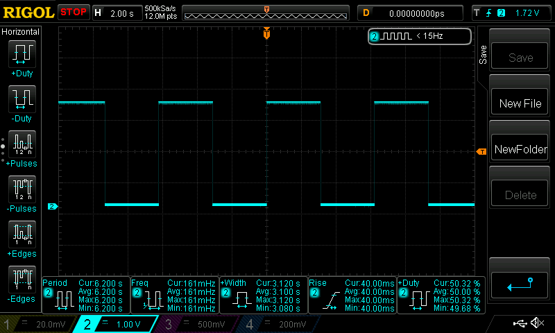
Width = 3.12 s = sweep time
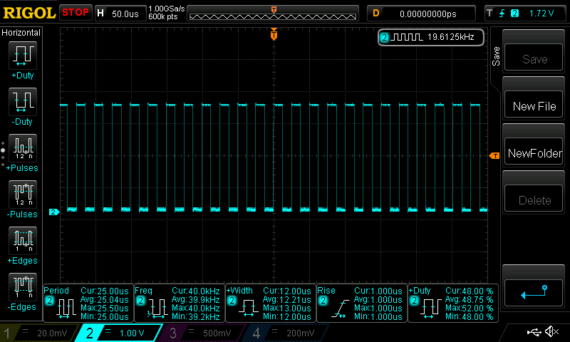
Test 02: 3 channels using 1 timer - using non-thread-safe API.
Width = 1.02 s = sweep time
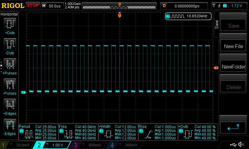
Test 03: 2 channels using 1 timer - using thread-safe API.
Width = 2.1 s = sweep time
Test 04: 2 channels using 1 timer - using non-thread-safe API.

Width = 1.02 s = sweep time
Conclusion
I believe this proves that the issue is solved. The new LEDC block will allow the user to select both the thread-safe and non-thread-safe APIs.
RE: PWM LED Control issue
-
Added by martin van beek over 5 years ago
Hi Dhanika,
Thanks for your investigation and sharing the results with us.
When I look to the results you've found, my conclusion should be that everything looks fine for the ThreadSafe timer operation.
The frequency is set to 1024Hz and should result in a period timing of approx. 2ms at the gpio5 pin toggle, as we also can see in your screen copies of the oscilloscope.
The ThreadUnsafe pictures will show very fast gpio5 pin toggles, but that's because you toggles the gpio5 pin every time you get back into the 'forever loop'.
The right place to toggle the pin is where you reset the duty cycle from 1024 back to 0, like this way:
duty = duty + 1;
        if (duty == 1024)
{
            duty = 0;
            gpio_level ^= 1; //toggle sweep period io pin
        }
I will look forward to the new waijung blockset update, then i'll test this PWM timing issue again.
Thanks so far Dhanika, kind regards,
Martin.
RE: PWM LED Control issue
-
Added by Dhanika Mahipala (ดานิก้า) over 5 years ago
Hi Martin,
The right place to toggle the pin is where you reset the duty cycle from 1024 back to 0, like this way:
No Martin. For the Tests related to the plain c code I purposely toggled at the beginning of the loop because I was not trying to measure the sweep time but the approximate time for one execution cycle. By measuring the cycle time I wanted to show how the execution time change when using the two APIs. If I had put the toggle inside the IF condition as you have showed I would have got the sweep time. After concluding on the problem, for the tests using Simulink I measured the sweep time to show that the problem is solved when using a different API since the initial question was addressed using sweep time.
We will be releasing the next version of Waijung2 soon.
Best Regards,
Dhanika
RE: PWM LED Control issue
-
Added by martin van beek over 5 years ago
Okay Dhanika,
Now I see what you've trying to figure out.
That's great when the API is instantiated every millisecond time step, this will solve this timing issue.
I'll wait for next release of this nice Waijung2 blockset.
Thanks so far and have a nice day, regards,
Martin.