Forums » Req. WJ2(ESP32) support »
 Assigning all tasks to CPU1, while letting CPU0 handle high speed timer interrupts
Added by Panagis Vovos over 5 years ago
Thanks to Waijung2 support team I can use this fabulous kit to execute some high speed sampling and calculation tasks, needed for power converter applications, using timer interrupts up to 0.0001s!
Of course, another collection of low speed control tasks must operate in parallel, in order to collect data from the system sensors and produce appropriate modulation signals. However, in order to have such a balance between control and actual execution someone has to specify the core that this fast-triggered piece of code is executed, so the rest (e.g. control) works undeterred at the slower rate.
As I have already being informed by Dhanika in Waijung , timer interrupts are handled by CPU0. That leaves CPU1 available for the execution of the control code.
So, in theory, for this application I would just have to use Waijung2 xTaskCreate block to create a separate task for the control algorithm and assign it to APP_CPU (CPU1). However, currently (waijung2_20.11b) xTaskCreate block does not have the functionality to assign the task which it creates, to a specific core.
Is there something you can do about that block, since there is such a functionality in the original xTaskCreate command.
That would be awesome and would make this fabulous tool complete for such applications.
Thank you for your time, anyway,
Grateful,
Panagis
Replies (7)
RE: Assigning all tasks to CPU1, while letting CPU0 handle high speed timer interrupts
-
Added by Dhanika Mahipala (ดานิก้า) over 5 years ago
Hello Panagis,
Please download the ZIP file attached and follow the steps below to install the patch for xTaskCreate block to your current waijung2 installation.
1. Close Matlab (which the waijung2 is installed in) if it is running.
2. Unzip the attached file (esp32_timer_interrupt_block_patch.zip) and copy and paste the content to replace the files at the location,
[ your waijung2 installation directory ]\waijung2_20.11b\waijung2\targets\esp32\src\blocks3. Restart Matlab.
I created a simple demo test_xTask.slx to demostrated how you can accomplish your objective. Please let me know if you want to any details about this. I tested the setup in this demo for a short period of time and it seems to be working as expected.
Please test and let me know whether this resolves your issue.
Here are the attachments mentioned,- Patch file for the block - esp32_xtaskcreate_block_patch.zip
- Model file to test the the new block - test_xTask.slx
Regards,
Dhanika
RE: Assigning all tasks to CPU1, while letting CPU0 handle high speed timer interrupts
-
Added by Panagis Vovos over 5 years ago
Dear Dhanika,
First, I had to change your Simulink model a bit (attached TaskMux.slx), in order to accommodate the design requirments.
The final aim of the test case is to have two separate tasks:
- One running at "max speed" , i.e. with the 0.0001s period and
- another one performing some "control" by manipulating the results of the other, but at a much slower pace.
The original model did not "exchange" data and results between tasks, which is a fundamental operation in power converter control.
So, I kept the 0.0001s interrupt that increases the counter (as we had in previous models) BUT created a task, per your advice/model, on CORE 1 that just checks the output of the counter every 0.1s and if this is above a threshold (i.e. halfway) then switches on the LED/GPIO2.
Good news is that the task on CORE 1 has absolutely no effect on the timer interrupt precision and vice versa. I tested it by changing the counter with an ADC block (model TaskMuxADC.slx) and some more calculations with the existing conter. The new model executed the same way as the previous, simpler one. So, the fast sampling rate with the timer interrupt serviced by CORE0 has not been affected by the primitive control of that sampling on the task running on CORE1.
However, it seams like the 1.5s/h delay noticed from the timer interrupt at 0.0001s rate in our previous communication, seams to have increased to 2s/h. Of course this half a second does not cause a serious problem to the control part of the code, which is needed anyway. However, it makes me worried whether the code is actually split between cores 0 and 1 as mentioned above. In order to add more to the confusion, I have changed the CPU assigned to the Ctrl_Algo to 0 in TaskMuxADC.slx. In other words, I assigned both timers/codes to the same core and it worked again just fine! Is the TaskX core selection still inactive and it assignes all tasks to Core 1 by default, indifferent of the selection within the block? Is there any chance that by mixing calculation flows between tasks/cores everything is assigned to one Core, indifferent of our initial intention?
I hope I did not confuse you more than helped with my tests. Thank you for your time and effort.
Panagis
| TaskMuxADC.slx | TaskMuxADC.slx | 37.9 KB | |||
| TaskMux.slx | TaskMux.slx | 37.9 KB |
RE: Assigning all tasks to CPU1, while letting CPU0 handle high speed timer interrupts
-
Added by Dhanika Mahipala (ดานิก้า) over 5 years ago
Dear Panagis,
The behavior you have explained is strange. Please give me sometime to look into your model files and hopefully give you a proper explanation.
Regards,
Dhanika
RE: Assigning all tasks to CPU1, while letting CPU0 handle high speed timer interrupts
-
Added by Dhanika Mahipala (ดานิก้า) about 5 years ago
There is a method to read the core in which that specific code block is executing. If you build any model file and place the line, ets_printf("Core ID: %d\n",xPortGetCoreID()); in any subsystem, ISR or task, it will print out the core that is used for the execution. I used your TaskMuxADC.slx model file and changed the timer interval of the high speed task to 0.1 sec since I'm going to place a print command inside the ISR. The result is as shown below:

- Control Algo Task = Subsystem that is connected to the xTaskCreate block to run the Control Algo task.
- Control Algo ISR = Since in this model the xTaskCreate block is run by a timer module, the ISR of the timer passes the semaphore to run the control algo task. This line is generated from this ISR.
- High Speed ISR = The high speed task subsystem is directly connected to the Timer block. Therefore the code generated by the subsystem will directly be placed inside the ISR of the timer. This line is generated from this ISR.
I was wrong on suggesting a second timer to drive the Control Algo task. The Control Algo ISR gets executed in CORE 0. Therefore instead of using a second timer I used a Function-Call generator block from Matlab Simulink block set and achieved the following result:
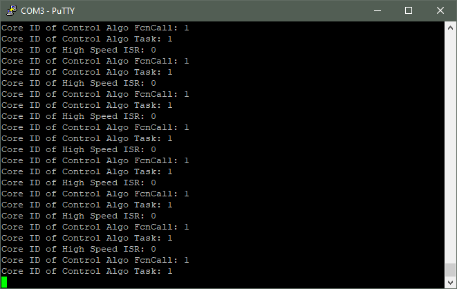
- Control Algo Task and High Speed ISR is the same as above.
- Control Algo FcnCall = Since in this mode the xTaskCreate block is run by a Function-Call, Another FreeRTOS task passes the semaphore to run the control algo task. This line is generated from this FreeRTOS task.
In conclusion after changing the second timer to a Function-call generator block everything seems to be functioning as expected. Could you please run the test on the TaskMuxWithFuncCall_18b.slx model file and check whether the drift still exist.
Model files:
RE: Assigning all tasks to CPU1, while letting CPU0 handle high speed timer interrupts
-
Added by Panagis Vovos about 5 years ago
Dear Dhanika,
Thank you for your help. Yes, we can confirm now that the tasks are loaded on the right cores.
No, the drift is minimal, so If it doesn't dramatically increase for some reason, it shouldn't be an issue for my work, and any practical power converter application to be honest. There is always a control algorithm, anyway, that "absorbs" such imperfections during actual operation.
However, can we test, somehow, if this drifting changes with the workload of each task (of course, assuming that it CAN run in the available time slot)? I am not familiar with changing the code, but could you please do some dummy for-loop or something in the slow and the fast loop to use up more of the available time slots for each task, so that we can see if it affects drifting?
Thanks,
Panagis
RE: Assigning all tasks to CPU1, while letting CPU0 handle high speed timer interrupts
-
Added by Dhanika Mahipala (ดานิก้า) about 5 years ago
Dear Panagis,
Assuming that you want to be able to add a for loop using Simulink I've prepared a simple model file (delay_mechanisms.slx). I've used For Iterator Subsystem from Matlab. Please note that the GPIO block does not serve a purpose. I merely placed it there because if a Terminator block is placed instead, the for loop does not get generated inside the ISR.
I hope this answers your question. Please do not hesitate to contact us if you have further questions.
Best regards,
Dhanika
RE: Assigning all tasks to CPU1, while letting CPU0 handle high speed timer interrupts
-
Added by Panagis Vovos about 5 years ago
Hello Dhanika,
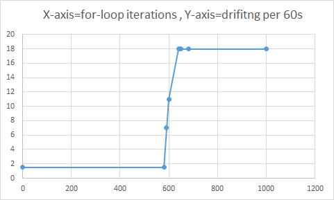
I just finished the sequence of tests. Attached you will find the code I used to run my tests. As you can see, I have added you "delay" inside the fast-triggered routine in a way that it forces simulink to actually use the number of iterations and do some maths, so that I can see the impact sooner. Yes, the results are impressive. The X axis is the number of iterations in the for loop and the Y axis is the delay.
1) As you can see, up to ~580 iterations there is absolutely no impact to drifting: that is kept to ~1.5s / 60minutes.
2) Then, from 585-640 iterations there is a linear relationship between number of iterations and drifting.
3) At approximtely 650-680 iterations I get a weird message:
[1B][0;31mE (10296) task_wdt: Task watchdog got triggered.
The following tasks did not reset the watchdog in time:[1B][0m[1B][0;31mE (10296)
task_wdt: - IDLE0 (CPU 0)[1B][0m[1B][0;31mE (10296)
task_wdt: Tasks currently running:[1B][0m[1B][0;31mE (10296)
task_wdt: CPU 0: main[1B][0m[1B][0;31mE (10296)
task_wdt: CPU 1: IDLE1[1B][0m
...which repeats itself for ever.
4) Beyond that point (>690 iterations) I finally get the typical "Core panic'ed..." error message on the Serial Port explaining that there is not enough time for the interrupt to finish execution before the next one is triggered:
[1B][0;32mI (296) cpu_start: Starting scheduler on PRO CPU.
[1B][0m[1B][0;32mI (0) cpu_start: Starting scheduler on APP CPU.
[1B][0mGuru Meditation Error: Core 0 panic'ed (Interrupt wdt timeout on CPU0)
Core 0 register dump:PC : 0x400e1ae0 PS ....
I can only speculate the following: RTOS allows some "marginal" interrupt tasks to finish their execution, even if there is not enough time between triggering events. I refer to the 585-640 range of for-loop iterations. Maybe it also doesn't know when this time is up exactly - that would have the same result. This means that it waits for the "marginal" task to finish execution and then returns to the main execution branch, at the expense of triggering accuracy of course. So, the longer the interrupt task, the longer the drifting. I cannot explain this linear relationship between the for loop and drifting otherwise. Mind you that the for loop is giving a proportional delay with respect to number of iterations. Some other way of delay would probably not behave this way.
So, Dhanika the question for 1M$ follows. Can you, somehow, see through your code if the interrupt task (this time the timer interrupt) is still in execution when the next interrupt triger? Maybe RTOS is not exactly aware of this, so maybe what you will be able to see is that the interrupt task finishes at, for example, the end of the 750 for-loop iterations and then the normal code starts executing "immediately" after and then back to the next interrupt etc., meaning there is no gap between 0.0001 sample time slots at the end of the interrupt task. There is no time that the CPU is "idle" in other words.
I hope this helps anyway,
Panagis
| Graph.png | View Graph.png | 8.07 KB | Delay added at the end of task vs. drifting | ||
| TaskMuxADC_FULL_CPU.slx | TaskMuxADC_FULL_CPU.slx | 35.3 KB | The Test Case with the delay for-loop added at the fast-triggered routine. | ||
| Graph.png | View Graph.png | 12.8 KB | Graph of Drifting vs delay added at fast-triggered interrupt | ||
| TaskMuxADC_FULL_CPU.slx | TaskMuxADC_FULL_CPU.slx | 35.3 KB | The test case Simulink file used. |