10 ChannelAnalog to Digital Converter with push buttons to change LCD display
Download demo file ADC10Ch.7z
1 MultiChannel ADC Examples
Purpose
To measure the voltage with a 10-channel analog to digital module and display the reading on the LCD display. With the help of a switch, readings from different channels can be seen as in Figure 1‑1.

Figure 1-1: Measuring voltage using 10 channels ADC and displaying it through the LCD.
Figure 1‑2 shows a Simulink Model for 10 channels ADC and displaying the voltage readings through LCD display. Subsystem model consists of a following attributes.
- Subsystem is used to define a variable to hold the voltage reading up to 10 channels.
- Subsystem settings for LCD display.
- Subsystem for displaying the values obtained through the LCD.
- This subsystem can adjust the LCD display (page = 0 to 2) and receive input signal from the switch.
- Updating the page number of the current page after pushing the switch.
- Subsystem for the LCD display, showing the readings from channels 0-3.
- Subsystem for the LCD display, showing the readings from channels 4-7.
- Subsystem for the LCD display, showing the readings from channels 8-9.
- Digital input signal from the switch SW1 and SW2.
- Read the voltage from the 10 channel analog input.

Figure 1-2: Simulink Model for reading voltage using 10-channel and displays the results through the LCD
After downloading the model into STM32F4DISCOVERY, the module will start reading the voltage at 10 channels every 0.1 seconds. The values of the voltages will be stored in 10 variables (V1, V2, … , V10). This is shown in Figure 1‑3.

Figure 1-3: Subsystem for reading the voltage from 10 channel analog input
There are 10 readings which need to be displayed on a single LED screen and this is not possible. Therefore subsystem is made so to display readings from 0 to 3 at the start-up page. With the help of the switch, the display can be changed.

Figure 1-4: Subsystem for displaying the readings of the channels (0 to 3) on the LCD display
Figure 1‑5 shows the subsystem for adjusting the page number on display and receive input signal from two switching ports to see the next page and previous page. The subsystem will not work if no swtich is pushed.
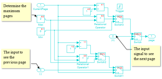
Figure 1-5: Subsystem for adjusting the LCD display