DC Motors Control
Download demo file Motor_Encoder.7z
1 DC Motor Control
1.1 Introduction
DC motor is a device that converts electrical energy into mechanical energy. DC motor structure consists of two main parts: a permanent magnet and a coil. There is also a brush which is connected to an external electric power to the coils of the motor. When coil is powered on, there is a magnetic field around the coil.
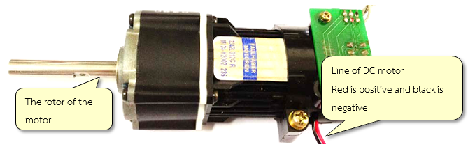
Figure 1-1: Example of DC motor
Figure 1‑1 shows the basic structure of DC motor. There are two lines of the motor i.e. black (negative polarity) and red (positive polarity). Rotation of the motor is based on the application of the voltage polarity applied to the lines of the motor. Motor can rotate in clock and anti-clock wise direction. The speed of the motor can be decreased by controlling the voltage of the power supply. The DC motor is cheap and easy to use. Use of DC motor is widely found in daily use items such as small toys, electric bikes, robotic arms and industrial projects etc.
DC motors typically operate at a voltage level which is not suitable for microcontroller to work. Therefore, DC motor cannot be directly connected to the microcontroller but with the help of current driver.
1.2 Drive Current for DC Motor
DC motor drive current is mostly an H-Bridge circuit which consists of a transistor which acts as a switch of 4 units (Q1 to Q4) via a dedicated DC motor. Figure 1‑2 (a) shows the position of the transistors in the H-bridge which are responsible for controlling the current in the motor. When sending the control signal to Q1 and Q4, Q2 and Q3 will be disabled and the current will flow from A to B which will enable the motor to rotate in one direction. This is shown in Figure 1‑2 (b)
When the control signal is sent to Q2 and Q3, Q1 and Q4 transistors will be disabled and current will flow from B to A and the motor will rotate in reverse directions. This is shown in Figure 1‑2 (c).
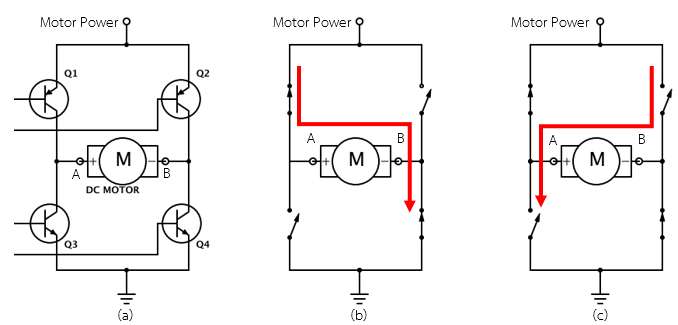
Figure 1-2: H-Bridge circuit for controlling the rotation of DC motor
H-bridge circuit can be easily found in integrated circuit form such as L293D or L298N which helps in the reduction of size and make it easy to use. PWM direction control signals can be of 1 bit or 2 bits as shown in Figure 1‑3.
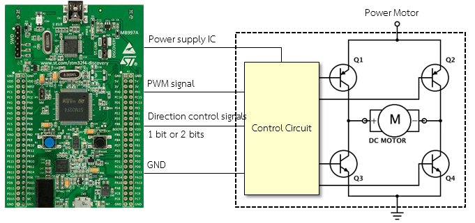
Figure 1-3: Connecting microcontroller with DC motor via control circuit
1.3 Equipment used in the Experiment
Figure 1‑4 shows aMG MotorCtrl2 board which is used in this experiment with a variable speed DC-Motor having a PWM signal on board which can drive current up to 1 A and can control the speed and direction of DC motor.
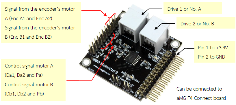
Figure 1-4: aMG MotorCtrl2 board
Figure 1‑5 shows how to control the direction of a DC motor using a control signal with the help of 2 bits which have 4 modes. These four modes are forward, reverse, brake and standby.
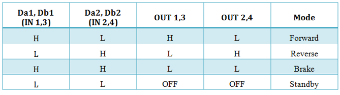
Figure 1-5: Using IC LB1836M [1, p. 3]
As far as choice of motors is concerned in this experiment, aMG MotorCtrl2 recommends using the interactive servo motor from Lego Mindstrom NXT. Following are the technical features of the motor.
- Gear set 1 : 48 for reducing the speed drive and increase torque at the tip;
- Encoder disc has 12 pulses per round. One round rotation can produce 180 pulses;
- The motor can run with a power supply of 7.5 – 9.0 V;
- Have RJ12 connector having current driver wire and also encoder signal wire.
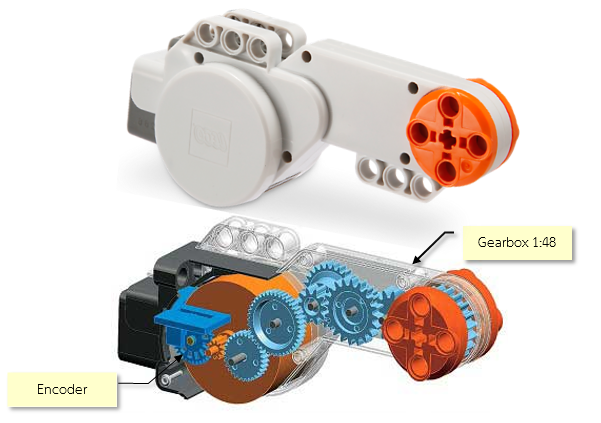
Figure 1-6: Interactive Servo Motor (Image provided by LEGO education)
1.4 Adjusting the Speed of DC Motor with PWM.
Aim
- Enable the users to understand the functions of the DC Motor current driver.
- Enable the users to adjust the speed of DC Motor with a PWM signal.
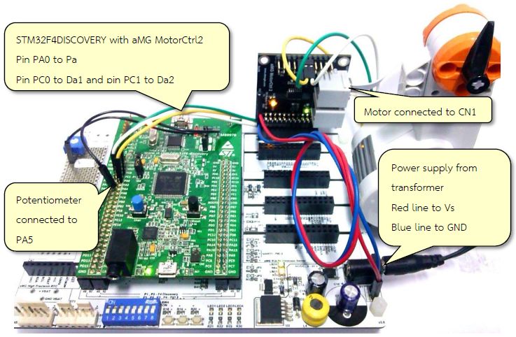
Figure 1-7: Device for adjusting the speed of motor
Figure 1‑7 shows the devices used for controlling the speed of the motor. The procedure for conducting this experiment is as follows.
- Install aMG MotorCtrl2 board on aMG F4 Connect If have no aMG F4 Connect board, can connect 3.3V and GND with STM32F4DISCOVERY
- Stand-by voltage for motor should be from transformer (5 to 9.0 V) connected on the aMG MotorCtrl2 board at pin VS and pin GND3.
- Connect the pin PA5 Potentiometer to adjust the Duty Cycle of the PWM (pin PA0).
- Connect PA0, PC0 and PC1 with pin Pa, Da1 and Da2 respectively.
- Lego Motor connected to the port CN1.
Figure 1‑8 shows the Simulink model for the experiment for controlling the speed of the motor. It consists of PMW with fine duty cycle (with the help of variable resistor). SW1 and SW2 switches are used to control the direction of rotation of the motor.
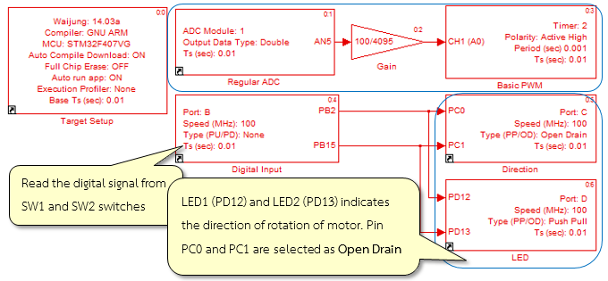
Figure 1-8: Simulink model for testing the speed of the motor
Download the Simulink model on STM32F4DISCOVERY board and connect the power supply with external power source. When SW1 switch is press and hold, the motor will start rotating in one direction as shown in Figure 1‑9. When SW1 is released, the motor will gradually stop (Standby). When SW2 is press and hold, the motor will start rotating in opposite direction. When both switches (SW1 and SW2) are pressed, the motor will halt suddenly (Break).
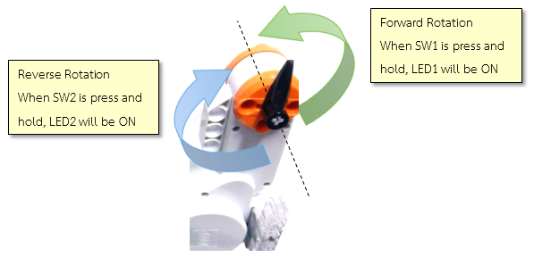
Figure 1-9: Indicates the direction of rotation with respect to the switches
Question: If user wants to use Potentiometer to adjust both speed and direction of DC motor without push button switch?
If the read value is more than 1.75V (which is the middle position of the potentiometer), start forward rotation and rotate it at maximum speed (the read value will be 3.3V at maximum speed). If the read value is less than 1.75V, start reverse rotation and rotate it at maximum speed (at maximum speed the read value will be 0V).
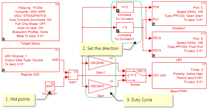
Figure 1-10: Simulink model for controlling the motor with a potentiometer
To analyze the condition, Simulink model is shown in Figure 1‑10 and the description is as follows.
- When reading, the value turns out to be in between 0 and 4095. In order to remove the midpoint (which is defined at 2047), the switching of potentiometer is done during 2048-2047.
- The direction of rotation can be determined by examining the logic, if the reading is greater than or equal to 0, then motor will rotate in forward direction and if the value is less than 0 then motor will rotate in reverse direction.
- The rotation speed adjustment can be done through duty cycle of basic PWM block, however, the value of the duty cycle turns out to be in the range of 0 to 100. Therefore, the value read from DC module must be divided into two cases as shown in Figure 1‑10.
2 Reading for Software Encoder
Position control or motion with the help of motor have many applications in the field of automation and robotics. In order to improve the speed and accuracy of the work, feedback control system is very important. The data form the motor speed reading is fed back to the processor to adjust the appropriate control signals.
2.1 About Rotary Encoder
Rotary encoder is an electro-mechanical device that measures the angular position or speed of rotation of the axes. It consists of a circular plate which is mounted to the spindle. Light sensor and photo detector array reads the optical pattern that results from the disc’s position at any one time which is shown in Figure 2‑1. The resolution measurement depends on the number of slots per cycle such as encoders with 180 number of channels can measure an angle up to 360/180 = 2.0 degrees.
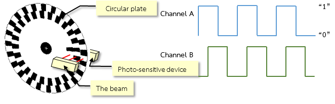
Figure 2-1: Structure of Rotary Encoder
When encoder’s axis starts rotation, channels on the disc will run through the light sensor. The photo detector on the receiving end will sense the light signal and when the sensor is connected with the signal circuit, the system can recognize how many degrees the motor has rotated.
From Figure 2‑1, one can observe that the discs are translucent in 2 rows and are overlapped. To detect the direction of rotation, such as the motor is rotating in clockwise (CW) direction or counter clockwise (CCW) direction, can be done by measuring the phase difference between the Channel A and Channel B signals. If the signals from Channel A is leading from signals of Channel B then the motor is moving in clockwise direction and if the signals from Channel A is lagging behind Channel B, then the motor is moving in counter clockwise direction and this is shown in Figure 2‑2.
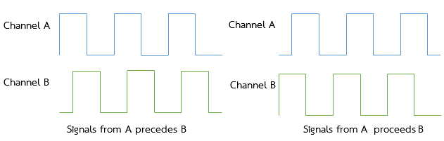
Figure 2-2: Characteristics of the signals from encoder with a phase difference of 90 degree
In order to detect the direction of rotation, pulse requires two sets of decoder circuits to indicate the rotational direction. The CW and CCW rotation have 0 and 1 values respectively. Based on the readings of the decoder, the count signal will be increased or decreased.
In addition, another advantage of using signals with the phase difference of 90 is that the user can adjust the resolution of the count which is shown in Figure 2‑3.
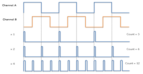
Figure 2-3: Signal encoder interfaces Quadrature
Channel A signal is chosen to be a reference signal. When the rising and falling edges of the channel A is equal to 3 then the count is (x1). When the rising edges and falling edges of the signal is equal to 6 (which is two times the number of pulses of the signal) then the count is (x2). When the rising and falling edges of the signal is 12 then the count is (x4) which is actually four times the number of pulses of Channel A signal.
If the encoder disc has 180 channels then how to count four times? Since the number of channels per cycle is equal to 180 x 4 = 720 slots thus the lowest possible resolution is 360/720 = 0.5 degrees and so on.
STM32 microcontroller family with a detection module and external signal read signals from encoder software which is the part of timer module. When connected to a signal from the encoder, both Channel A and Channel B to the microcontroller, the counter will count up or down to the rhythm of the received signal. This allows the user to reduce the process of programming. Just set the timer modules per line and then the counter that counts is immediately applied.
In this section, description will be given, how to read values from STM32F4DISCOVERY board with encoder module and timer. All 15 modules that can interface with the encoder has 6 sets of timer 1, 2-5 and 8
This lesson will show how to read values from the STM32F4DISCOVERY board, encoder module with Timer, but all 15 modules that can interface with encoder has 6 sets of Timer 1, 2 – 5 and 8 [2].
2.2 How to use Encoder Read
The encoder block is in Simulink library >> Waijung Blockset >> STM32F4 target >> On Peripheral Chip >> TIM and have the following characteristics and properties.
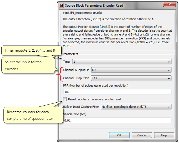
Figure 2-4: Characteristics of Encoder Read Block
The purpose of Encoder Read Block is the count the signals from the encoder both from Channel A and B. If both channels are selected then the maximum count will be equal to 4 x pulse per revolution (PPS). The output direction is the direction of rotation which is either 0 or 1. If ‘reset counter after every count read’ is selected then the counter will be reset to zero after reading the count.
2.3 Reading the Angle of Rotation of the Motor
Aim
- The user can count the encoder to measure the position of the swivel.
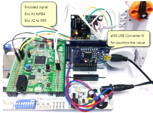
Figure 2-5: Circuit for experimenting with the encoded signal from encoder software
Figure 2‑5 shows devices which are used in this experiment for reading the signals from encoder with same set-up steps as in previous section experiment on speed adjustment but add the signal link, encoder and aMG USB Converter N board for sending position read from encoder through USB.
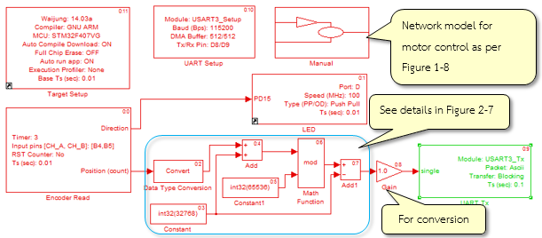
Figure 2-6: Simulink model for reading the signals from encoder software
Figure 2‑6 shows a Simulink model for this experiment to read signal from the encoder. It contains Subsystem block for controlling the speed of motor with Potentiometer and push button switch as in Figure 1‑8. The value from Encoder Read Block is unsigned 16 bit integer. Figure 2‑7 shows an example of converting read value to signed integer.
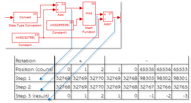
Figure 2-7: Method for converting Encoder Read Block to be a signed integer
Download the model on STM32F4DISCOVERY and then connect the USB cable to the computer and switch on the motor. The reading of the encoder will be displayed in TeraTerm window as shown in Figure 2‑8.
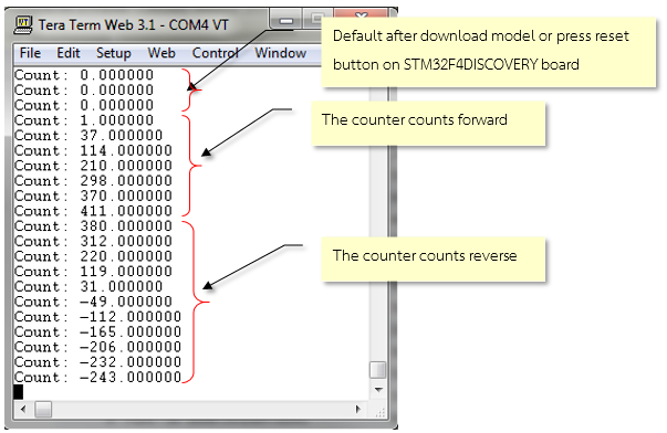
Figure 2-8: TeraTerm window reading the encoded signal
Value is in the unit of count pulses. To change the display unit such as degrees, user need to learn from the manual about the number of channels of the decoder end plate and then gain ratio of the transmission is adjusted accordingly.
For example, rotation of 1 revolution (360 degrees) of the pulse multipled by 4×180 to get 720 pulses per cycle if user wants to get the value in degrees.
Gain = 360 / number of pulses per revolution = 0.2.
To show the value of the unit.
Gain = 1 / number of pulses per revolution = 0.0014.
Signal oscilloscope is used to inspect the signal from pin Enc A1 and Enc A2 of aMG MotorCtrl2 board and is shown in Figure 2‑9.
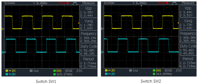
Figure 2-9: Signal from the encoder measured at the oscilloscope
3 References
- ONSemiconductor, “LB1836M Low-Saturation Bidirectional Motor Driver for Low-Voltage Drive,” 2013.
- STMicroelectronics, “STM32 F407xx Datasheet-production data [Online],” 2013.
- STMicroelectronics, “RM0090: STM32F40xxx Reference Manual [Online],” 2013.
- Bartelt, Industrial Control Electronic: Device, Systems & Applications, Newyork: Thomson Delmar Learning, 2006.
- Denney, “Incremental Optical Encoder,” [Online]. Available: http://thedenneys.org/pub/robot/encoders/. [Accessed Wednesday February 2002].
- Hurbain, “NXT motor internals,” [Online]. Available: http://philohome.com/nxtmotor/nxtmotor.htm. [Accessed 11 June 2014].