FiO2 and aMG Labkit – Blinky demo
1 Overview
- FiO2 is MCU (STM32F4IG) board designed to work with “aMG F4 Connect 2” motherboard. Power supply for FiO2 provided by this motherboard.
- In case of application require not use “aMG F4 Connect 2” or in a custom design motherboard, external VDD (3.3V), VDDA and VREF+ must be provided. Follow this guideline for external power supply connection: http://waijung.aimagin.com/index.htm?power_supply_connection.htm
- Require ST-Link programmer for Auto Download during build model, https://www.aimagin.com/st-link-v2.html
- Most of tutorial and demo file for STM32F4DISCOVERY can be used in FiO2 board, except ST-Link port connector and MCU pin size difference.
- Unlike the STM32F4DISCOVERY, FiO2 did not have other IC (sensor, usb, audio) located on the board, so there is no pins conflict. All pins available for user application.
2. Software requirements
- Matlab and Simulink with Simulink Coder and Embedded Coder or Real-time workshop.
- Waijung Blockset and STM32F4 Target, download from: http://www.aimagin.com/download
- ST-Link driver and ST-Link Utilities, available in Waijung package or download from: http://www.st.com/web/catalog/tools/FM146/CL1984/SC724/SS1677/PF251168?sc=internet/evalboard/product/251168.jsp
- Virtual COM port driver for aMG_USBConverter-N, available in Waijung package or download from http://www.ftdichip.com/Drivers/VCP.htm. Installation guide: http://www.ftdichip.com/Support/Documents/InstallGuides.htm
- Follow the Getting Started with Waijung & STM32F4 Target more explanation and installation guide: http://aimagin.com/blog/02-getting-started-with-waijung-stm32f4-target/
3. Power on the board and checking ST-Link connection
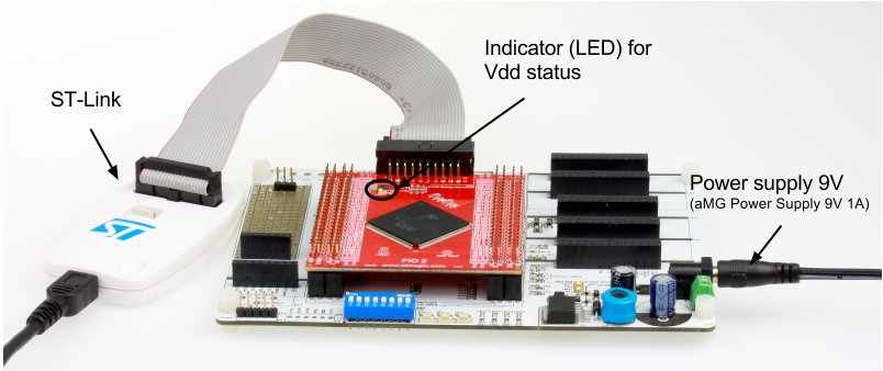
- Setup the board, connect ST-Link and Power supply as showing in below picture:
- Connect ST-Link USB to the PC, then run ST-Link utilities software
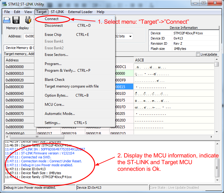
- Select menu “Target”->“Connect” for check the connection.
- Information of connection result will display. The message display the MCU device information indicate the connection Ok.
- Close the ST-Link software.
Note: after finish checking the ST-Link connection, ST-Link Utilities must be closed, to prevent connection error while Waijung run the Auto Compile and Download process during model build
4. Build and Run existing demo file (provided in Waijung packet)
The demo files for STM32F4 is located in the demo directory: waijungroot\targets\stm32f4_target\stm32f4\demo\
To run the existing demo for LED blinky, follow below steps:
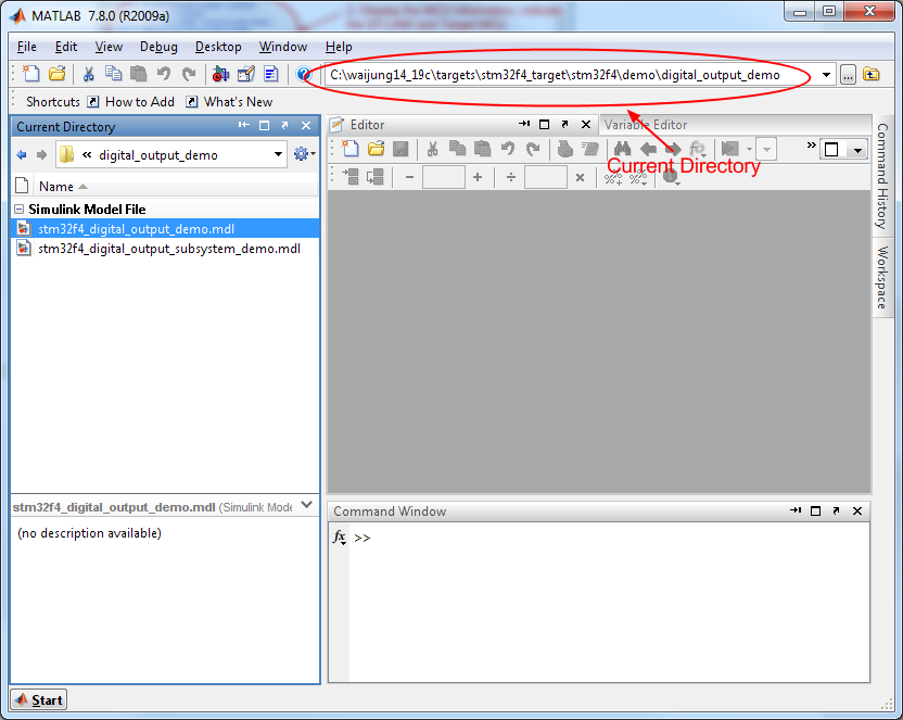
- Change the Current Directory (Working directory) to waijungroot\targets\stm32f4_target\stm32f4\demo\digital_output_demo
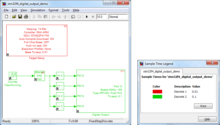
- Open demo model file: stm32f4_digital_output_demo.mdl
Note: Waijung root and model file path mode not containing space or unicode (non-English) character.
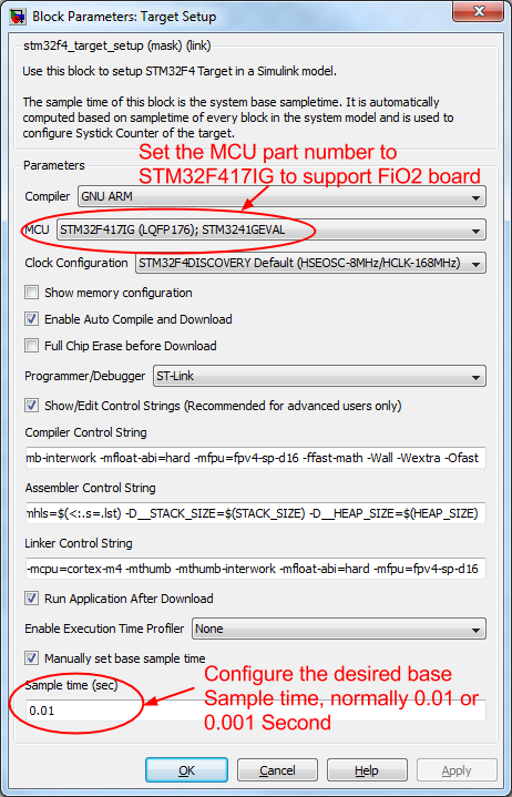
- Change configuration in Target Setup block for FiO2. Also sample time can be changed or leave it as default value.
- Update model by press Cntrl+D key (Update diagram). Normally required repeat this update two times for all blocks to correct the sample time setting.
- Check the sample time value for the blocks, by press Cntrl+J key. The difference color indicate difference Sample time.
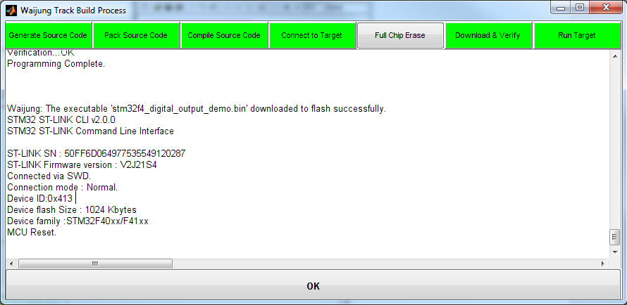
- Build working model (With Auto Compile and Download) into the Target FiO2 board. By press Cntrl+B key, Simulink will generate the required source file, then Waijung compile those source file with C compiler. When compile success, waijung will download (program) the output binary file via ST-Link automatically. The Waijung Track Build process indicates the result of each operation, as showing in below picture.
- After done above process, now the FiO board is running. Observe 4 LEDs flashing in sequence.
- Disconnect ST-Link from the board when finished process Auto Compile and Download.
5. Demo for Create new model
- At Simulink Library browser, select “new model” menu to create new model. Save model file, change the Current Directory to the location of this model file.
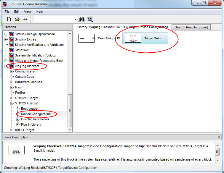
- Drag and Drop “Target Setup” block for STM32F4 Target into model.
- Save model again, then update model by press Cntrl+D key (2 times) for waijung to configure the model configuration at first time and correct Sample time value. IMPORTANT: do not build model without this update diagram (Cntrl+D).
- Design the model function.
- Build model, Auto Compile and Download to run in Target FiO board.