How to Drive Stepper Motors and RC Servo Motors
download all demo files: stepper.7z
1 General Use of Peripheral
This article discusses the use of powered devices such as stepper motors and RC servo motor using STM32F4DISCOVERY and Waijung Blockset.
1.1 Introduction to Stepper Motor
Stepper motor is a motor with a step rotation. It is a brushless DC electric motor that divides a full rotation into number of equal steps. Step size can be of 0.9, 1.8, 5, 7.5, 15 or 45 degree per step which is controlled by using a Digital Signal Controller (DSC). DSC is also responsible for controlling the direction and speed of the motor. Applications of stepper motors can be found in many ways of life such as printer, motion control positioning system, plotters, slot machines, camera lens etc. Stepper motor has the following features;
- Fully rotates 360 degrees continuously;
- The control does not rely on the detection of rotation;
- Don’t use a brush, therefore it cannot be worn (however rotor causes some noise);
- Control by digital circuit of microcontroller conveniently.
Typical stepper motors (two phase stepper motors) can be divided into two categories: Unipolar and Bi-polar as shown in Figure 1‑1 and Figure 1‑2 respectively. A unipolar stepper motor has one winding with center tap per phase. Each section of winding is responsible (switched on) for each direction of magnetic field. A bi-polar motors have a single winding per phase and current in the winding need to be reversed in order to reverse a magnetic pole which makes the driving circuit little complex as compared to unipolar motors.
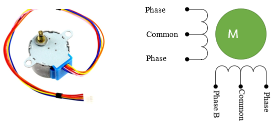
Figure 1‑1: The external and internal structure of unipolar stepper motor
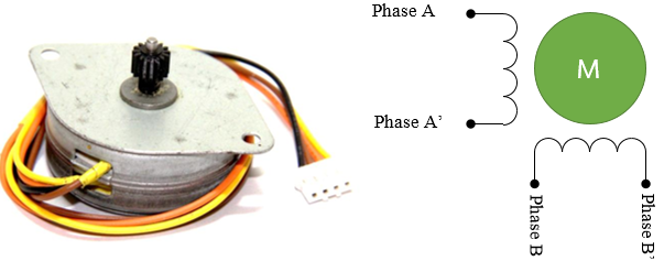
Figure 1‑2: The external and internal structure of bi-polar stepper motor
Control rotation of Uni-polar stepper motor can be performed by controlling the current which is sent to coil of each phase in certain order. If we want to let current flow in any phase, that phase will have logic state “1”. We can control rotation of stepper motor by 3 approaches.
Single Phase Rotation Control or Wave Drive: To transfer current into coil of stepper motor, one by one as the sequence shown in Table 1‑1 (1 means voltage transferred into the coil, 0 means no voltage). So currents in coils will have same direction. This style will have result as low drive force in stepper motor, so it is not famous approach.
Table 1‑1: Single phase rotation control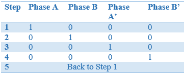
Two Phase Rotation Control or Full Step Drive: To transfer current in both coils at the same time and transfer current consecutively as per Table 1-2. This technique gives more current to the motor and motor will have more power.
Table 1‑2: Two phase rotation control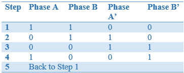
Half Step Rotation Control: To transfer as Two Phase and Single Phase alternatively. This is shown in Table 1‑3.
Table 1‑3: Half Step rotation control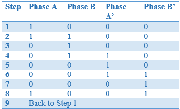
Speed of rotation of the stepper motor axes is based on the time delay. If the time delay is less than the core will rotate faster and if the time delay is more than the core rotation will be slow.
1.2 Introduction to RC Servo Motor
Radio Control (RC) servo motor consists of a small electric motor driving a train of reduction gears. A potentiometer is connected to the output shaft which is responsible for measuring the position of the output. These values are then compared continuously with the commanded position of the radio control and in case of any difference between the output value and the commanded value, error signal is generated which instructs the motor to change its position accordingly. Due to RC servo motor light weight and cheap price, their applications can widely found in small scale robotics, steering of a car etc.
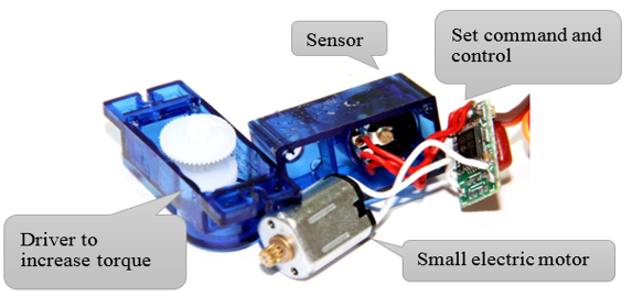
Figure 1‑3: Internal components for RC servo motor
2 Experiment for Controlling Stepper Motor
2.1 Equipment Used for this Experiment
Control devices such as stepper motor can be used to create a high driving torque flow. Microcontroller cannot be directly connected with the motor (as microcontroller pins cannot provide the required amount of current to run a motor) therefore current driver is placed between the motor and the microcontroller. For example, the board aMG Step Motor Driver IC ULN2003 can supply up to 500 mA current for controlling a unipolar stepper motor.

Figure 2‑1: Characteristics and features of stepper motor used for this experiment
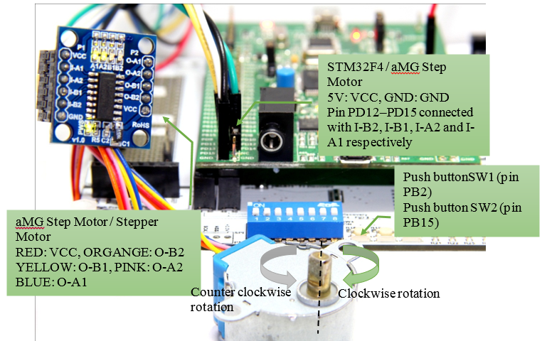
Figure 2‑2: Using stepper motor with STM32F4DISCOVERY
2.2 Experimenting the Rotation Axis of Stepper Motor
Purpose of the Experiment
- Enable the user to learn the structure and control of the rotation axis stepper motor;
- Enable the user to create Control Subsystem Block for stepper motor;
- Structure and Active Control Subsystem Block for stepper motor.
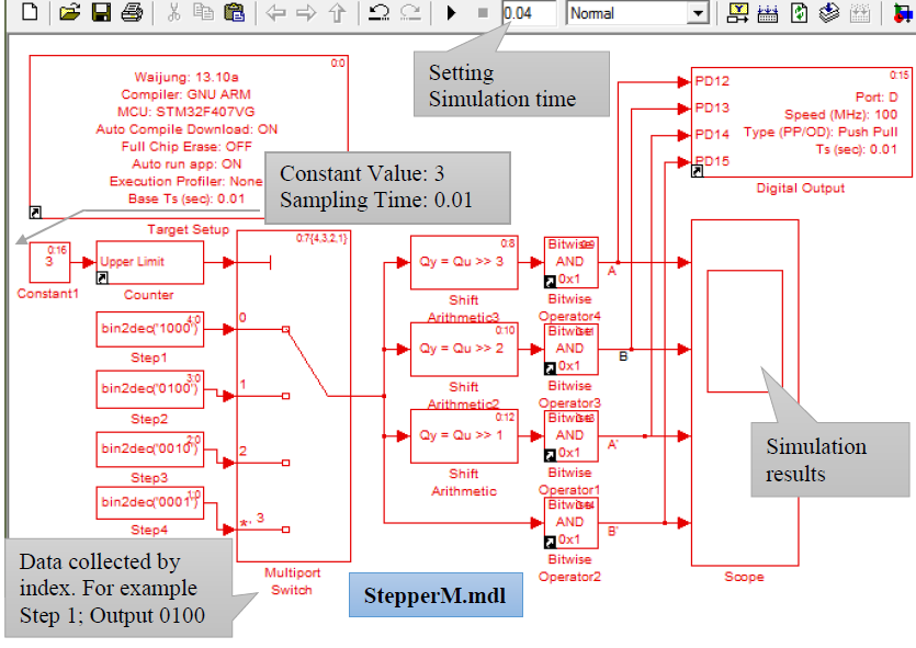
Figure 2‑3: Simulink model for controlling the rotation of single phase stepper motor
Table 2‑1: Simulink block model for controlling the rotation of single phase stepper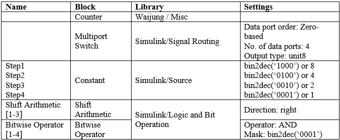
When users download Simulink model into STM32F4DISCOVERY aMG F4 Connect, the LED lights on the board (aMG Step Motor) will run in a sequence. The axis of the stepper motor will rotate at a constant speed (counterclockwise). Users can adjust the values of the Counter Limited Block Sampling time. This section will enable the users how to create Subsystem Block in Simulink for the use of stepper motors. Compared to writing a program in C for Subsystem Block, it is very convenient to do using Simulink as user only need to set the Input and Output ports. Creating and using Subsystem Block for the stepper motor involves the following steps;
- Subsystem Block are placed in Simulink Library >> Ports & Subsystems as shown in Figure 2‑4;
- Double click on the Subsystem Block on a window of the Subsystem, a new window will appear. In1 and Out1 Block which are used as Input/output of Subsystem Block.
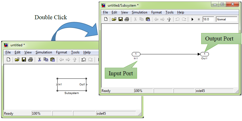
Figure 2‑4: Creating Subsystem Block in Simulink
- Create Simulink model as shown in Figure 2‑5 in windows Subsystem Block. 1 input is for receiving the step’s values and have 4 port output is for connecting with digital output. Users can add In1 and Out1 Block from Simulink/Ports & Subsystems Library.

Figure 2-5: Subsystem model for controlling stepper motor (single phase)
- When we want to connect with input port of Subsystem Block with Counter Block for receiving step’s values in range of 0 – 3 and connect with output port of Subsystem Block with digital output including Scope Block. For see the result of simulation, please refer to Figure 2‑6
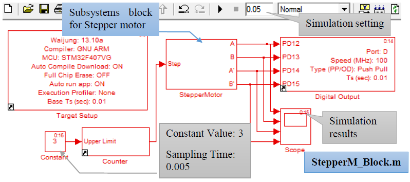
Figure 2-6: Simulation model for controlling the stepper motor Subsystem Block
If users want to control the two phase rotation, this can be achieved by fixing the value of the Constant Block as shown in Table 1‑2: Two phase rotation control, Figure 2‑7 respectively.
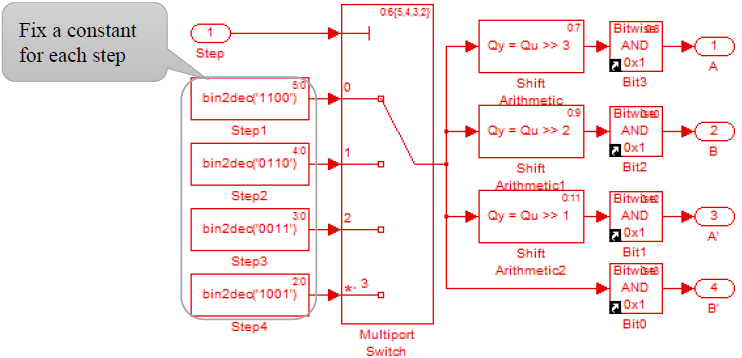
Figure 2-7: Simulation model for controlling the stepper motor (two phase
If users want to control the phase rotation, this can be achieved by increasing the number of data ports in the Multiport Switch and fix the value of the Constant Block as shown in Figure 2‑8 and Table 1‑3.

Figure 2‑8: Simulation model for controlling the stepper motor (half phase)
2.3 Experiment for adjust rotation direction of stepper motor.
Objective of the Experiment:
- To let user able to control axis rotation of stepper motor with push button switch. Rotate clockwise when push the switch SW1 and rotate counterclockwise when push the switch SW2.
- Enable the users to control the direction of the rotor by changing the order of current transferring in the coil. For example Step 1 à Step 2 à Step 3 à Step 4 à Step 1 for counterclockwise and Step 1 à Step 4 à Step 3 à Step 2 à Step 1 for clockwise.
- In the beginning, user will create the Subsystem Block for Counter Up/Down named CntUpDown (Figure 2‑9) having 3 input ports to set maximum count value i.e. count up, count down and 1 output port for send step to Stepper Motor Block (as described in previously).
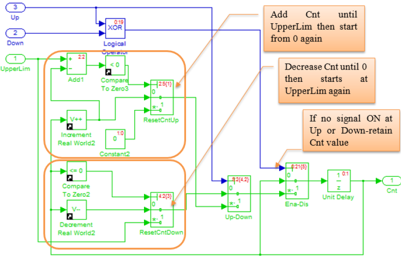
Figure 2-9: Subsystem Model for Counter Up/Down
For block that is the important part to increase or decrease are Increment Real World and Decrement Real World (Library Simulink >> Additional Math & Discrete >> Additional Math: Increment – Decrement)
From Simulink (Figure 2‑10) set Constant Block Value = 3 to set CntUpdown to count value between 0-3 (note: If want to control half-phase, set Value = 7) and set Sampling Time = 0.005.
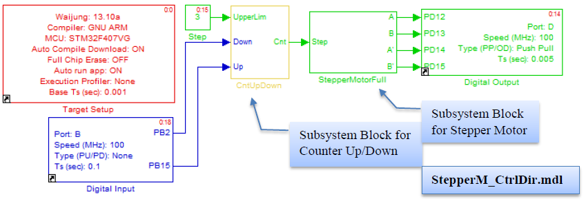
Figure 2-10: Simulink Model for rotation direction of stepper motor by push button switch
When Simulink model is downloaded into STM32F4DISCOVERY, then the Digital Input Block will read logic state from SW1 and SW2 (connected to pin PB2 and PB15) every 100ms and then send the signal to CntUpDown Block to control rotate direction. Results will be:
- When push and hold SW1, the Counter value will be decreased, stepper motor will rotate clockwise.
- When push and hold SW2, the Counter value will be increased, stepper motor will rotate counterclockwise.
- When push or release both buttons (SW1, SW2) at the same time, the Counter value will be stable. The rotor of Stepper Motor is locked at the same position because no current in the motor’s coil.
- User can adjust rotation speed by adjust Sampling Time in Constant Block.
This can apply to use in various applications such as manual-type feeder, adjust the view angle in safety camera etc.
2.4 Experiment for adjust rotation speed of stepper motor with DIP switch.
Objective of experiment:
- To study structure and speed adjustment for stepper motor with DIP switch
- User can create Trigger type Subsystem Block to control speed of stepper motor
Rotation speed of stepper motor can be performed by time delay in each step. The disadvantage of Simulink model is users are unable to adjust Sample Time of Source Block in the model after downloaded into STM32F4DISCOVERY.
We can set the value of Subsystem Block to start or execute internal program when have external signal by put the Trigger Block in Subsystem Model (Fig. 2-11)
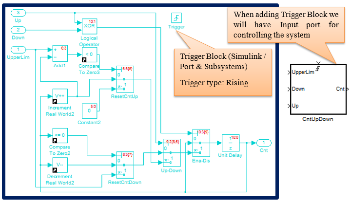
Figure 2-11: Adding Trigger Block in Subsystem Model
Add Digital Input Block to read signals from DIP Switch and Multiport Switch to select signal from Pulse Generator Block that have a pulse width 50% and setting period values as in Figure 2‑12.
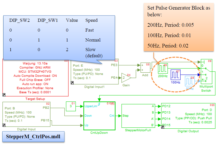
Figure 2-12: Simulink Model for adjusting rotation speed of stepper motor with DIP switch
User can set DIP Switch as shown in table (in the above figure) to adjust rotation speed. For example, when all positions are set to OFF, CntUpDown Block will work every 0.005 second (positive edge signal will occur every 0.005 second) and stepper motor will rotate when SW1 switch is press and hold. When set DIP Switch all “ON”, system will go to Default condition then CntUpDown Block will be working every 0.02 second therefore the stepper motor will rotate slower.
2.5 Experiment for control position of rotor axis with push button switch.
Objective of experiment:
To study structure and able to control position of rotor axis with push button switch by rotating the axis 90 degree clockwise when SW1 is pushed and rotate the axis 90 degree clockwise when SW2 is pushed.
Controlling the axis is an open loop system because no signal from the sensor is sent back into microcontroller. Thus the system can know the position of rotor axis by number of steps that has been sent to stepper motor to let STM32F4DISCOVERY identify the current position of stepper motor’s axis. User can add the position calculation part into CntUpDown Subsystem Block (Figure 2‑13)

Figure 2-13: Subsystem Model for count step that sent to Stepper Motor
Position controlling of axis of stepper motor can follow these steps:
- Set the desired step and check the current step (get from Subsystem as in Figure 2‑13). In this experiment we set counterclockwise as “+” and clockwise as “ –“
- Compare and calculate StepToGo with the equation:
StepToGo = Desired Step – Current Step
- Let stepper motor rotate until StepToGo = 0
From the properties of stepper motor in the experiment, Step Angle: 5.625 degree / 64 means motor rotate 1 step the axis will rotate 0.0879 degree, so if we want to rotate 90 degree.
Desired Step = 90 / 0.0879 = 1024 Step

Figure 2-14: Simulink Model for control position of the axis of Stepper Motor
After downloading the Simulink model into STM32F4DISCOVERY, the motor axis will rotate 90 degree counterclockwise or +90. When push reset, the current position will be deleted from memory so the motor will rotate again to the position +90.
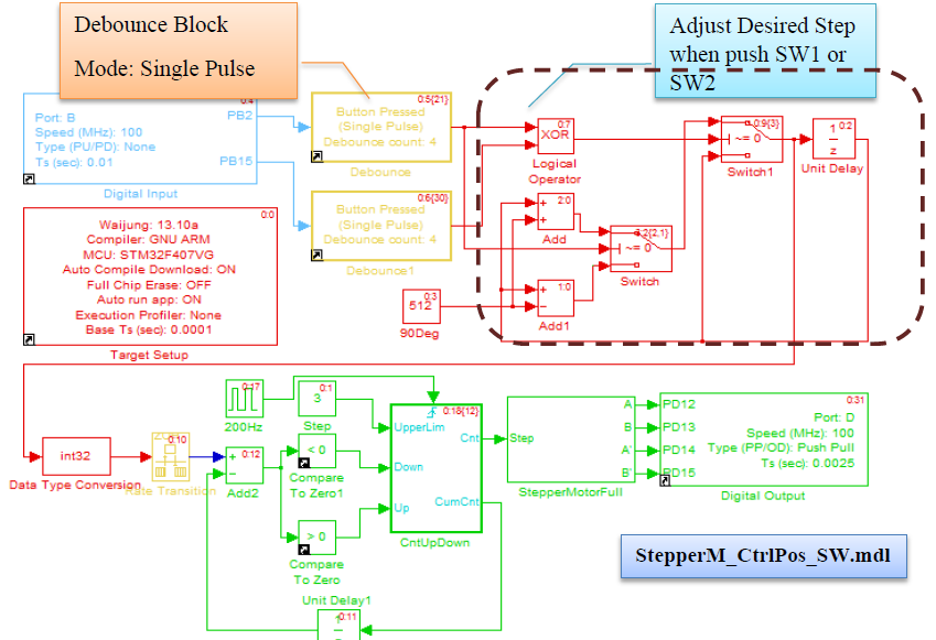
Figure 2-15: Simulink Model for control position of axis of Stepper Motor with push button switch
3 Experiment for control RC Servo
3.1 Equipment for experiment
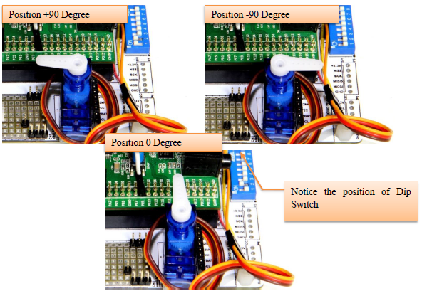
Figure 3-1: Using of Servo with STM32F4DISCOVERY
RC Servo receive digital signal to change the axis’s angle in the form of Pulse Width Modulation (PWM). Position controlling module of RC Servo will check time of signal at state “ON” or pulse width then adjust the position as programmed by its manufacturer. Figure 3‑2 shows the estimated width of ON signal for controlling the SG90 RC Servo with signal period 20ms. If user use other model of RC Servo they should study its detail in datasheet especially its voltage and pulse width.
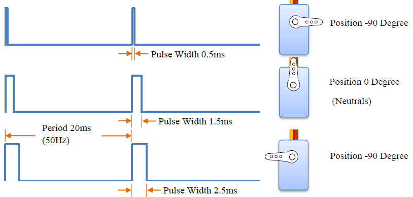
Figure 3-2: Width of signal ON or %Duty Cycle for control position of RC Servo
3.2 How to use basic PWM Block
In the section Digital Input/Output is described using Pulse Generator Block to generate signal that user can only set the %Duty Cycle in the block. In this section, we will also describe how to use Basic PWM Block to generate PWM using Timer of STM32F4DISCOVERY. User can select Timer and Channel to send signal to external devices such as RC Servo or DC Motor controller and able to configure the %Duty by Simulink.
The basic PWM Block is in Simulink library >> Waijung Blockset >> STM32F4 target >> On Peripheral Chip >> TIM that has the properties as given below.
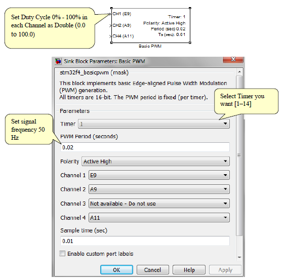
Figure 3-3: Properties setting of Basic PWM Block
3.3 Experiment for control RC Servo position with DIP switch
Objective:
- User can control position of RC Servo by using basic PWM Block
- User can select %Duty by using DIP switch
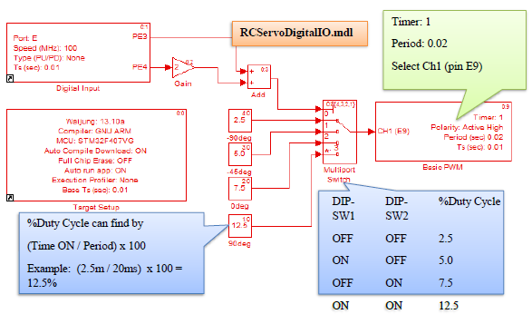
Figure 3-4 Simulink Model for control RC Servo position by DIP switch
Figure 3‑4 shows Simulink model for control RC Servo position by DIP switch. Digital Input Block read the signal from DIP-SW1 and DIP-SW2 which are connected to PE3 and PE4 respectively. Received signals will be translated to decimal form (between 0-3). Multiport Switch will select %Duty Cycle related to Index and then send to Basic PWM Block.
After downloading the program into STM32F4DISCOVERY, PWM signal will be sent to RC servo. As a result, the motor will rotate to the position of %Duty Cycle of PWM signal. When all DIP switch are at the position “OFF” – rotated to the -90 degree position. When all DIP switch are “ON” – rotated to the +90 degree position. When SW1 is ON then motor will rotate to -45 degree and when SW2 is ON the motor will rotate to the 0 degree or origin.
Problem: If user wants to set RC Servo to be at 0 degree (Pulse Width = 1.5ms), what %Duty Cycle of PWM is needed if signal frequency = 60 Hz?
Answer: Signal = 60 Hz means Period = 16.67 ms. Then %Duty Cycle can be calculate => 1.5ms x 100/16.67ms = 9.0 %
.png)
Figure 3-5: Experiment for control RC Servo with DIP Switch
3.4 Experiment for control RC Servo with Potentiometer
Objective:
- Enable the users to control RC Servo position by adjusting %Duty Cycle with variable resister (Potentiometer)

Figure 3-6: Simulink Model for control position of RC Servo with variable resister
Figure 3‑6 shows Simulink model for controlling the position of RC servo with variable resister. ADC read electrical voltage at pin PA5 then that value will be transformed to %Duty Cycle by linear relation equation between ADC Value (0 – 4095) and %Duty Cycle as shown in Figure 3‑7.

Figure 3-7: Linear relation between ADC value and %Duty Cycle
RC Servo will rotate to any position depending upon the voltage value. When resistor is connected to the GND, motor will rotate to -90 degree position (%Duty Cycle = 2.5). When resister is connected to VDD (or 3.3 V), motor will rotate +90 degree position (%Duty Cycle = 12.5). Figure 3‑8 shows the positions of RC Servo at each value of voltage read from A5 pin.
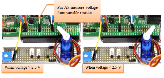
Figure 3-8: Experiment to control RC Servo with potentiometer
4 References
- Kiatronics, “28BYJ-48 Stepper Motor,” [Online]. Available: http://www.sensors.co.nz/datasheet/28BYJ-48 Stepper Motor.pdf.
- The MathWorks, “Documentation Center,” The MathWorks, Inc., [Online]. Available: http://www.mathworks.com/help/simulink/ug/creating-subsystems.html
- Laidman, “Stepper Motors and Control, Part I – Unipolar Stepper Motor and Control,” 1999. [Online]. Available: http://www.stepperworld.com/Tutorials/pgUnipolarTutorial.htm.