How to Drive a Character LCD
Download all demo files: clcd.7z
1 Using LCD Display
Computer users can read messages or see pictures via monitor such as Cathode Ray Tube (CRT), Liquid Crystal Display (LCD) and high resolution Light Emitting Diode (LED) monitors. It is not feasible to connect embedded systems such as microcontroller with big screens.
LCD display module as shown in Figure 1‑1 display simple text such as status of the sensor, temperature/pressure of an environment etc. This direct connection is easy to do and energy efficient as well.
1.1 Understanding the LCD Display
The LCD display includes a liquid crystal screen and control display (LCD controller). LCD controller is responsible for controlling the message on the display screen such as line spacing, line breaks and an ON-OFF pixel to represent a character or image. Character and language which is displayed on the screen depends on the manufacturer. For example, Hitachi HD44780 LCD controller supports English as well as Japanese characters [1].The LCDs which are connected to the microcontroller can be categorized into two types i.e. character LCD and image (graphical LCD) as shown in figure below.
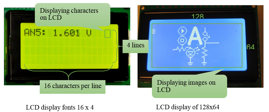
Figure 1‑1: Character and graphical LCD
It is worth mentioning that LCD has more features as compared to 7-segment display still it is easy to connect the LCD with the microcontroller as compared to 7-segment, although LCD costs more as compared to 7-segment display.
In Thailand, text LCD controller are more popular and graphical LCDs do not support Thai characters.
2 Experiment with LCD
2.1 Equipment Used for the Experiment
Figure 2‑1 shows the experimental set up for using aMG CLCD2, which includes a LCD display of size 16×4 and the board. When connecting the STM32F4DISCOVERY with aMG CLCD2, STM32F4DISCOVERY and aMG F4 Connect2 need to be powered through the adapter for fully functional display (normally STM32F4DISCOVERY is operational when powered through USB).
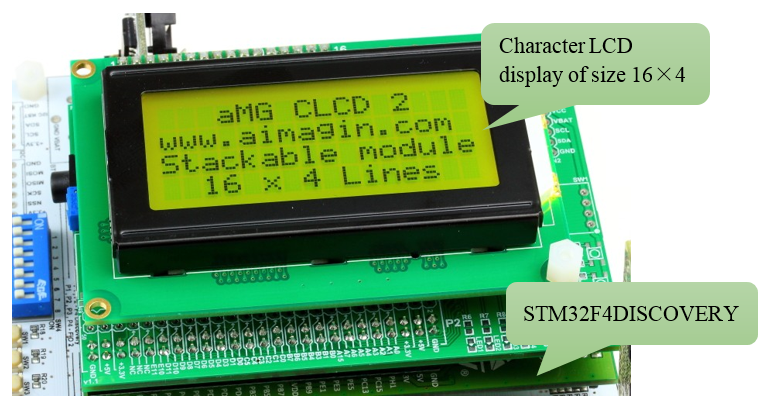
Figure 2‑1: aMG CLCD2 board
2.2 Two Line LCD Display
Purpose
- For a user to learn how to use character LCD block and data storage block for different messages?
In Waijung Blockset block, there is a related module called aMGCLCD2 in the library which can be accessed via Waijung Blockset>> Hardware Modules >> Character LCD. Figure 2‑2 shows the block parameters of Character LCD Setup. GPIO has two ports. One port can be used for sending control commands and other port can be used for sending text.
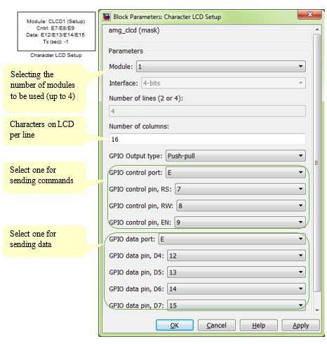
Figure 2‑2: Block parameters for Character LCD Setup
Now the question comes, how LCD knows where to send the data from the user within the LCD? The answer is simple. User need to mention the coordinates (xpos, ypos). (0, 0) is the point at the top left corner of the screen (which is the starting and reference point) and (15, 3) is at the bottom right corner, which is the last one.
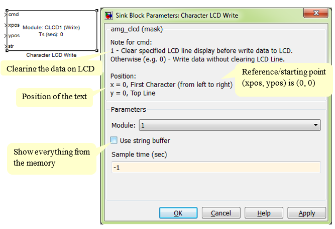
Figure 2‑3: Characteristics of Character LCD Write Block
Character LCD Write Block is a text input block for display and is used for message passing using a two line LCD volatile data storage block. It is located in Simulink Library >> Misc >> Data Storage.
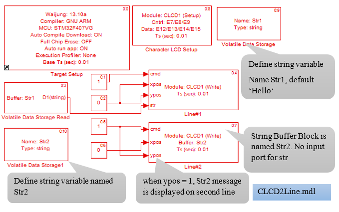
Figure 2‑4: Simulink model for two line LCD display
Figure 2‑5 shows the use of character LCD Write Block in two ways.
- When using the string buffer, the user must add volatile data storage read block for reading text from a variable and a character LCD Write Block
- When using string buffer, user need to define variables to be displayed in character LCD Write Block.
In variable ‘str1’, the default text is ‘Hello…’ and message ‘Welcome to Waijung’. Str2 contains number of letters and spaces.
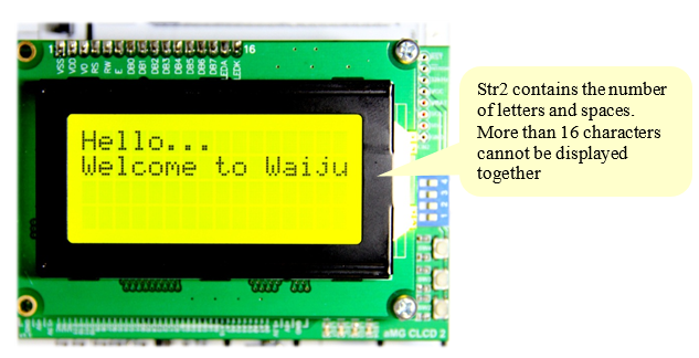
Figure 2‑5: Two line LCD display
2.3 Experiment for Color LCD Display
Purpose
- Enable the users to display variables and read values from ADC or source block
- Enable users to create a subsystem block to use with LCD display
This experiment will display a text stored in a constant. User need to edit the model and download it again if wish to display data which changes over time such as counting the number or reading and displaying the value of sensor at regular intervals of time. This feature is not available for Character LCD Write Block because the type of the variable.
Print Block, located in the Library >> Waijung Blockset >> Misc serves as a decimal number converter (Double and Float) or an integer. It means that string can be displayed on the LCD. The Simulink model for the example explained above is shown in Figure 2‑6. Following are the settings for Printf Blocks.
- Printf1 Block, printf format: Hello…
- Printf2 Block, printf format: Waijung Tutorial.
- Printf3 Block, printf format: Index: % d.
- Printf4 Block, printf format: AN5 Value:%1.3f.
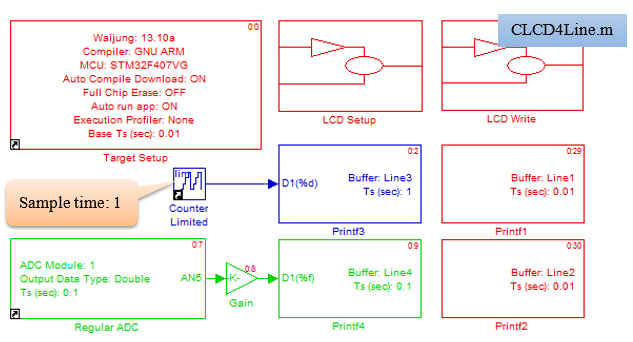
Figure 2‑6: Simulink block for color LCD Display
CLCD and LCD display settings are shown in Figure 2‑7 and Figure 2‑8 respectively.
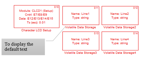
Figure 2‑7: Default settings for CLCD and assigning a string
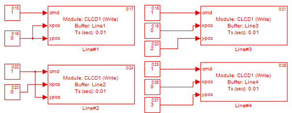
Figure 2‑8: For color LCD display line
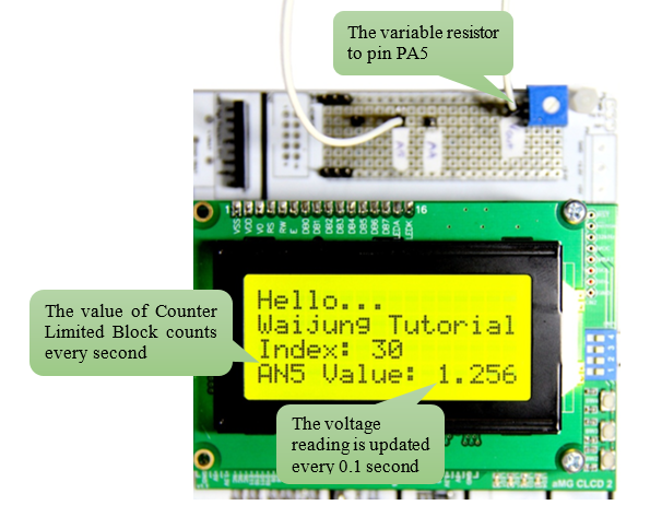
Figure 2‑9: Experimental results for color LCD display
The first two lines shown in in Figure 2‑9 are set to be fixed with no change throughout the experiment. The working of STM32F4DISCOVERY starts from line 3. The 4th line reflects the changes in the voltage when the value of variable resistor is changed.
2.4 Text Button Experiment
Purpose
- Enable the user to learn a Enable Subsystem Block
Simulink model shown in Figure 2‑10 consists of Enabled Subsystem Block which can be found in the Simulink Library i.e. Simulink >> Ports & Subsystems. The program will work within Enabled Subsystem when the switch button in the Enabled Subsystem Block is ON. 4 lines are printed as shown as follows and information about the subsystem block is shown in Figure 2‑11.
- message1 Block, Printf Format: Embedded system
- message2 Block, Printf Format: is just a
- message3 Block, Printf Format: mini computer
- message4 Block, Printf Format: system
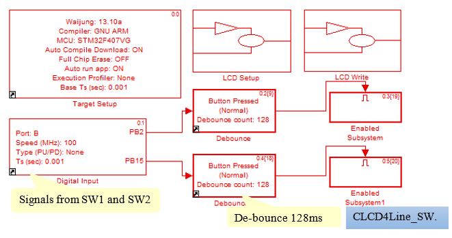
Figure 2‑10: Simulink model for displaying text with keypad
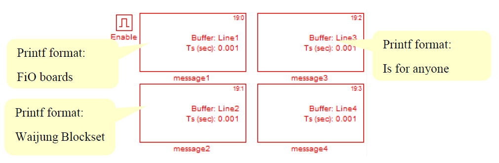
Figure 2‑11: Subsystem block information
Download Simulink model into STM32F4DISCOVERY. When SW1 is ON message ‘FiO boards and Waijung Blockset is for anyone” will be displayed. When SW2 in pressed then the message “Embedded system is just a mini computer system” will be displayed on the LCD as shown in Figure 2‑12.
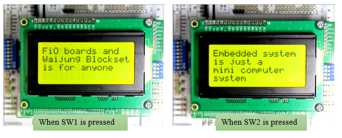
Figure 2‑12: Displaying different messages on LCD by pressing Switch buttons