How to Read Thermocouples
Download demo file Thermocouple_demo.7z
1 Use of Transducing Thermocouple
1.1 Introduction
Transducers, which are used for measuring the temperature, are of many types such as RTD, thermistor, and temperature sensing ICs etc. Thermocouples have exceptional properties which are mentioned as follows
- Wide range measurement
- Can be used in high temperature environment
- Highly sensitivity
- Cheap, robust and easy to use.
Therefore it is a popular device [1] both for daily use applications and industrial purpose, for example, measuring the temperature inside the oven, gas turbine machine, diesel machine, and industrial process.
Some disadvantages of thermocouple are: very less linearity compared to RTD or specific designed IC (those are more sensitive and accuracy). Moreover, output signal of thermocouple is very low (estimated 40 mV/°C for K-Type thermocouple). Users have to use complex signal adjustment circuit for high resolution, signal amplification, signal compensation, etc [2].
Despite of the disadvantages mentioned above, the advantages prevail and they are very popular choice now days.
1.2 What is a Thermocouple?
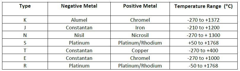
Thermocouple is a device which is used for measuring differential temperature. Thermocouples are made up of two different metals. One is set to be positive type metal and another one is set to be negative in nature. Table 1‑1 shows the properties of each thermocouple [3]. Each type has different range of measurement.
Table 1‑1: Types and properties of each thermocouples
If we connect two different type of metals as shown in Figure 1‑1, electric voltage that is created in the circuit due to difference of temperature between two points is known as “Seebeck”. The process to convert temperature into electric voltage is given in equation (1).
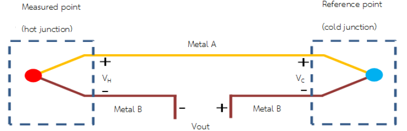
Figure 1‑1: Working of thermocouple that results from Seebeck phenomenon
Figure 1‑2 shows the principal of general thermocouple. Two lines of metal are connected from the end and another end is left open, having connection to third metal (copper wire). Copper wire is the electrical medium between the two metals and the system which results in an additional connection point. As long as the temperature of the two connections and copper wire are equal, there is no effect on the output voltage (Vout)
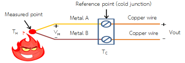
Figure 1‑2: Principle of general thermocouple
Following relations govern the principle of thermocouple.
V out = V H – V C ........................................................(1)
V out = α(T H – T C) ....................................................(2)
where;
- Vout is the voltage which is measured between the measured voltage at hot junction and the reference voltage (cold junction).
- V H and V C are the voltages due to different temperature between two points.
- α is Seebeck coefficient which is equal to the Vout divided by the temperature difference.
Thermocouple, which is shown in Figure 1‑2, the output voltage is the function of product of difference between temperature at hot and cold junction and Seebeck coefficient and is expressed in (2). Thus when we know the temperature at the cold junction and output voltage, we can know the real temperature at hot junction.
Considering a simple example, if the temperature at cold junction is 0°C (Tc = 0°C) then Vout = V H. In this case, the measured temperature will be the same as that of hot junction. Referring to the National Bureau of Standards (NBS) which lists the relationship of electric voltage and temperature of each thermocouple with reference to the cold junction at 0°C.
Setting the cold junction at 0°C is not easy in the real world, so if the temperature is not 0°C, we have to know the value of temperature at the cold junction to calculate the measured temperature (at hot junction). Then the output voltage have to compensate this discrepancy. This process is called “Cold-Junction Compensation).
Thermocouples have different types depending on the purpose of use as shown in Figure 1‑3.
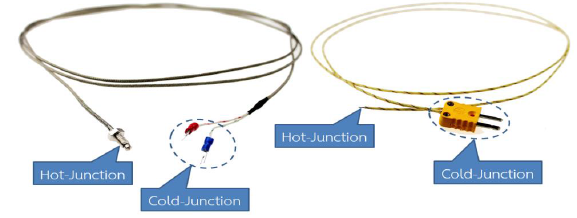
Figure 1‑3: Example of K-type thermocouple
1.3 Thermocouple Selection
Because thermocouple has many good properties as mentioned earlier, so it is very common commodity in many industrial applications. Selection of suitable thermocouple has to consider the following factors:
- Temperature measuring range;
- Tolerance from chemicals and corrosion;
- Tolerance form vibration;
- Location of installation (geographic, mechanical, screw, etc.);
- Examples of thermocouples which are used in industries are shown in Figure 1‑4.
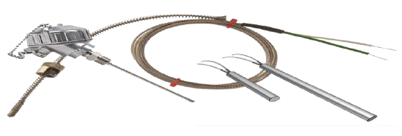
Figure 1‑4: Popular thermocouples for industries use
2 Introduction to aMG Sense-Thermocouple
aMG Sense-Thermocouple is a module for receiving analog signals from thermocouple and transform them into 14 bits digital signal. These 14 bits digital signal becomes the input of the microcontroller that has a SPI interface having signal conditioning circuit and cold-junction compensate function to make the temperature measurement more accuracy.
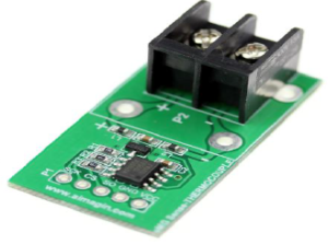
Figure 2‑1: Digital temperature measurement circuit, aMG Sense-Thermocouple
General Information about aMG Sense-Thermocouple is as follows.
- Digital module is used with the thermocouple;
- Uses MAX31855 IC from Maxim Integrated;
- Cold-Junction compensated function;
- Support thermocouple types K, J, N, T, S, R, and E;
- Measured data is in 14 bits signed binary and scaling detail is at 0.25°C;
- Connected to microcontroller with SPI, read only;
- Measurement range is from -270°C to +1800°C
- Accuracy of ±2°C at the range -200°C to +700°C when used with type-K thermocouple. For other type & range, see the reference [1]
- Able to detect GND or VCC of the thermocouple;
- Able to detect when is not connected with thermocouple;
- Have example circuits and software;
- RoHS standard.
Applications can be found in general equipment, industries, temperature control system, HAVC vehicles etc.
2.1 Basic Connection
aMG Sense-Thermocouple, temperature measuring module, has 2 signal connection points. P1 is output signal module which will be connected to the microcontroller through SPI protocol. P2 is signal receiving point which receives output signal from thermocouple. Connections at each point must ensure that poles are correct.
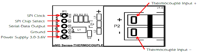
Figure 2‑2: Functions of each connect points on the board
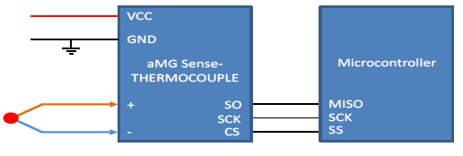
Figure 2‑3: Connection between module and microcontroller
2.1.1 Recommendation for Use:
To prevent the failure of the device, following things must be noted.
- Voltage should be in between 3.0 – 3.6 VDC;
- Source current in between 900 – 1500 mA;
- External temperature range is -40°C to 125°
2.2 Principle of Working
This module comes with built-in signal conditioning circuit and cold-junction compensator which makes the use of the device easy for the users. Module comes in a small compact size and also have the ability to reduce noise from signal guide from thermocouple. Before the measured data is translated into the temperature values at the measured point, compensation for the difference between cold junction sides must be taken into account. For type-K thermocouple, the relation is given by equation (3).
VOUT = (41.276µV/°C) x (TH – TC) (3)
Where
- VOUT is output voltage of thermocouple (µV)
- 41.276 is sensitivity coefficient (µV/°C)
- TH is measured temperature or at temperature at hot-junction (°C)
- TC is temperature at cold-junction (°C)
In this function, when the temperature at cold-junction is changed, the measured value is still accurate. The principle to measure temperature at measure point (-270°C to +1800°C) of this module is that – first measure the temperature inside the chip (-40°C to +125°C) via precise measurement assuming that the value should be equal at all cold-junction points. Then measure the output voltage of thermocouple through ADC module. All the measured values will be used to solve equation (3) to find TH, the already compensated value and transformed to signed binary data. Notice that at some range, the value at hot-junction is lower than cold-junction.
From the principle above, to make highly efficient measurement, we must prevent heat that might affect the chip (temperature should be same in all area of the module) to prevent the measurement error.
2.3 Data Connection in Serial SPI
Data communication between the module and the microcontroller is uni-directional SPI, as in Figure 2‑4. Read only begin at microcontroller creates logic LOW at CS pin and generate a clock signal at 5 MHz into SCK pin. Module will send processed data at SO pin. The measured value and already compensated value need 14 clock signals. All data need 32 clock signals. The first sent out bit is the 31st bit (sign bit of thermocouple temperature). Error and temperature value will be updated when logic at CS pin is HIGH again.
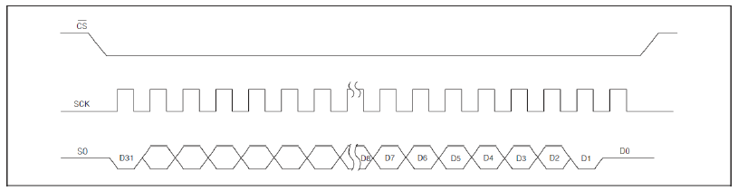
Figure 2‑4: Protocol for SPI module
From Table 2‑1, measured temperature begins from bit D[30:18] ordered from MSB to LSB bit. D16 is normally in LOW state and will be HIGH if error occurs such as no connection to thermocouple, short circuit between thermocouple and VCC or GND. Reference temperature data has 12 bits begins from D15. If input point + and – of module has no connection with thermocouple, the D31 bit will be 0 and D[30:18] will be 1. Bit D0, D1, and D2 normally is in LOW state. Bit D2 will be HIGH when connector of thermocouple is short circuit with VCC. D1 bit will be HIGH when thermocouple is short circuit with GND and D0 bit will be HIGH if there is no connection between thermocouple and module.
Table 2‑1: Format of output signal from module
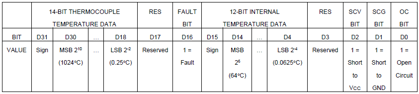
Table 2‑2: Example of data read from thermocouple
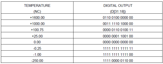
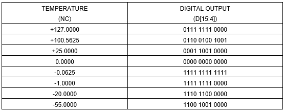
Table 2‑3: Example of data read from reference point
3 Experimenting with the Module
In these examples, aMG Sense-Thermocouple is used along with aMG Lab Kit – F4 with type-K thermocouple (-270 to +1372).
3.1 Experiment 1 – Reading the Data for processing it on PC
Devices to be used:
- 1 aMG Sense-Thermocouple board;
- 1 STM32F4DISCOVRY board;
- 1 aMG F4 Connect 2 board;
- 1 aMG USB Converter-N2 board;
- 1 type-K thermocouple.
Assemble STM32F4DISCOVRY board and aMG USB COnverter-N2into master aMG F4 Connect 2 board and then connect type-K thermocouple to input of aMG Sense-Thermocouple (check the poles carefully). Use jumper wires to make circuit as shown in Figure 3‑1.
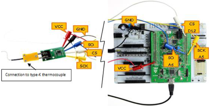
Figure 3‑1: Circuit for experiment 1
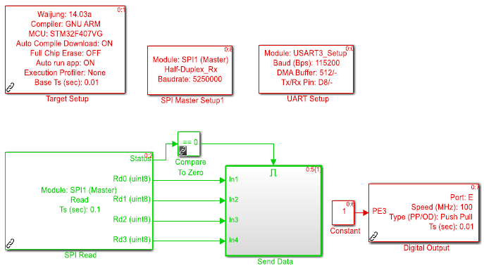
Figure 3‑2: Software at MCU
The pin PE3 of MCU board is set to HIGH state in order to cancel other sensors information which were used before. SPI Read Box will read data and store information in 8 bit variable. Thus, if the user wants to read 32 bits data, then user need to have 4 variables for that. First read position is LSB, but if the user wants first position to be MSB then Send Data Box need to be re-arranged as shown in Figure 3‑3.
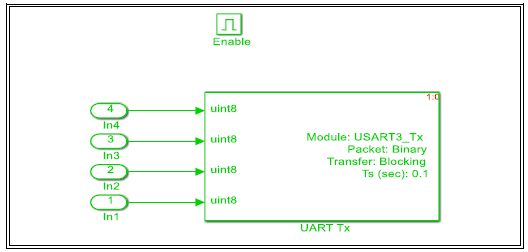
Figure 3‑3: Rearrangement of data in Send Data Box
From the manual reference [3], it is known that the maximum time to process data is 100 msec so sample time of SPI read is set to update every 0.1 seconds.
Software at host PC is shown in Figure 3‑4. Receiver on PC uses 32 bits variable. To extract the required data bits, Extract Bit Command Box is used. To converse signed binary into decimal, user can use Data Type Conversion box and then multiply by the Gain as in Table 2‑1.
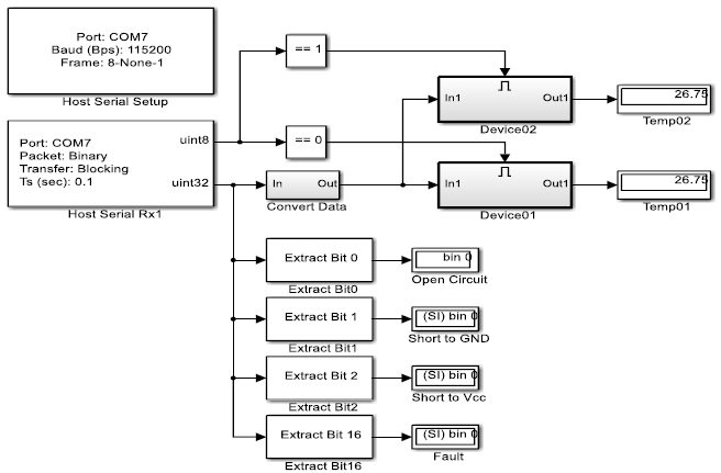
Figure 3‑4: Software at host PC
3.2 Experiment 2 – Reading the Data from 2 Thermocouples and Process it on PC.
In this experiment, the same equipment will be used as used in experiment 1 but one additional aMG Sense-Thermocouple board and a thermocouple will be used.
Connect the devices as in Figure 3‑5. These two modules use common VCC, GND, SO, SCK and connect to MCU at the same pins. CS pin of the existing module still uses D12 pin but the new module use D11 pin. Software at MCU is shown in Figure 3‑6.
With the help of Counter Limited and logical operator (NOT), alternatively HIGH-LOW signal is generated between pin D11 and D12 to choose the connection at the module. Logic LOW is used for data reading and logic HIGH is used for not to read the data.
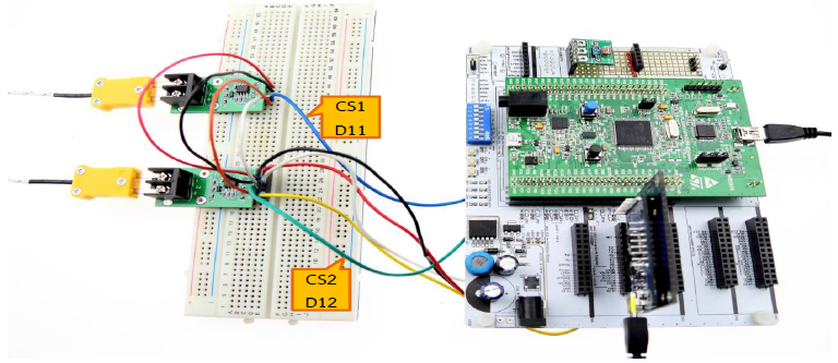
Figure 3‑5: Circuit for experiment 2
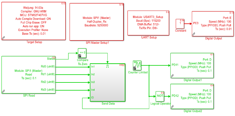
Figure 3‑6: Software at MCU
Software at host PC uses Compare to Constant to detect that data coming from which module? If the data is the same, it will sent output data “1” to display the received data.
When the temperature value is being displayed, the user can try pulling the thermocouple out or using a copper wire to short circuit the connection points of VCC and GND and observe the changes at bits 0, 1, 2 and 16. There should be 1 for each test condition.
.png)
Figure 3‑7: Software at host PC
3.3 Experiment 3 – Reading the Data from 2 Thermocouples and Display the Data on the LCD.
Devices and connections for this experiment are same as in experiment 2 with an addition of aMG CLCD 2 and aMG USB converter – N2 is removed from the circuit. The experimental layout is shown in Figure 3‑8 and example software at host PC is shown in Figure 3‑9. If user wants to have a clearer display of LCD then LCD must be connected to external power supply.
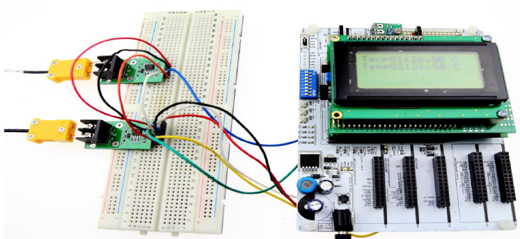
Figure 3‑8: Circuit of experiment 3 and LCD display
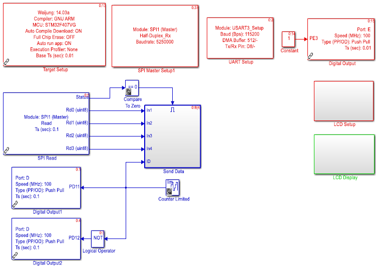
Figure 3‑9: Software at MCU
3.4 Connection with more than two thermocouples
This example describes only idea about software when more than two thermocouples are connected. Let’s assume that there are five thermocouples then software will be as in Figure 3‑10.
MATLAB function box for software at PC side has an sample program to find the mean (average) of measured temperature from each module.
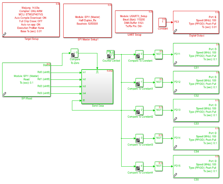
Figure 3‑10: Software at MCU
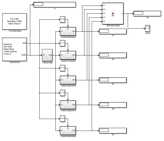
Figure 3‑11: Software at PC side