How to Use Data Logger
Download demo file datalogger.7z
1 External SD-Card
1.1 Introduction
In this article, description about how to read and write data on flash memory using a microcontroller is given. The limitation of this technique is that only data less than 1MB can be stored thus not suitable for big data processing.
SD cards are used for storing data (storage is non-volatile) and can retain the data in the memory without power as well. SD cards are often used in mobile phones, digital cameras etc. There are many types of SD cards available in the market. SD cards can be divided into three types which are shown in Figure 1-1.
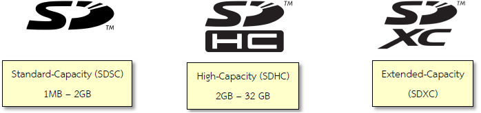
Figure 1-1: Identifying the types of SD cards
Figure 1‑2 shows the class of SD cards based on their speed of data transmission so that user can select these SD cards based on the requirement of the application whether the user is using it for recording high definition (HD) movie or general purpose storage.
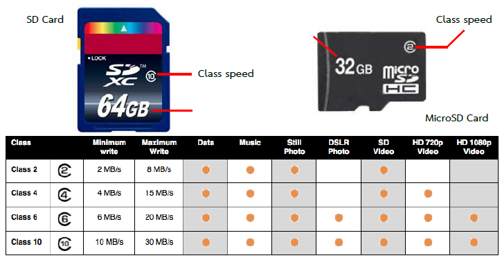
Figure 1-2: General Information on SD and Micro SD Cards
SD cards are compact and small is size and for this reason, they are the favorite choice to be used as a data storage device in embedded systems. SPI communication can be used to receive data from the SD card but STM32F4ISCOVERY has a STM32F407VG microcontroller which has specific management system of Secure Digital Input/Output (SDIO) [1]. Pin description of SDIO interface is given in Figure 1‑3.
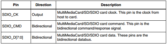
Figure 1-3: Input/Output port SDIO Interface
Each pin has the following functions.
Pin SDIO_CMD is for sending commands by CE-ATA to SD card and have the default settings of the SD card.
- Pin SDIO_CK is for the clock signal with the frequency between 0 MHz to 25 MHz.
- Pin SDIO_D[7:0] can be set to select the size of the bus (in terms of bits). If user selects 4 bits, then the information will be transmitted through the SDIO_D[3:0] cable and if 8 bits are selected then it will be SDIO_D[7:0]. If the size is not set then the information will be sent to SDIO_D0 only [2, p. 720].
As a SDIO interface, the cable has a multi-bit SDIO interface so that it can transfer data faster than the SPI interface. Figure 1‑4 shows the pin layout of the SD card when it communicates with SDIO interface using 4 bits.
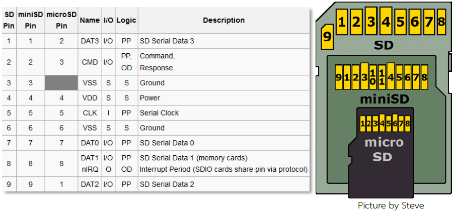
Figure 1-4: Pin Layout of SD, MiniSD and MicroSD Card in SDIO mode
2 Preliminary Experimentation with Data Logger
2.1 Introduction
Data logger is a device which is used to store data from various sensors. Generally data logger devices can be connected to the sensors directly. Data can be saved into the memory of SD card with the time stamp and users can access the data from the data logger later. Computers can also be used for reading the data from the memory and display it in various forms such as tables, graphs etc. Data logger devices can also be connected to the computers directly.
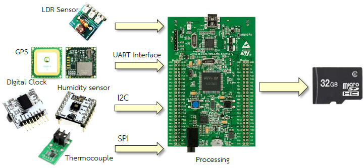
Figure 2-1: Applications of embedded devices to data logger
Data logger devices can be used in a number of ways such as recording the humidity of certain place or the temperature or the location of the vehicle using GSP etc. Data logger devices can operate in a stand-alone manner and able to read the signals from the sensor and save the information in their memory without the use of any additional software or peripherals to the computers. They are designed in such a way so that they can be installed easily where required.
Application of an embedded data logger is presented as an option because of their small size. Microcontrollers like STM32F4 family can receive the signals in a number of ways for example from analog to digital module, I2C, SPI UART, etc.
This article explains how to use the data logger block and how it can be used to record the voltage reading from ADC module into the memory of SD card and read the data from the SD card on the computer with the help of Microsoft Excel and Notepad ++. MATLAB is used to obtain the graphs.
2.2 Equipment used in the Experiment
For this experiment, a user must know the socket available for MicroSD card in aMG F4 Connect board and aMG CLCD2 which is shown in Figure 2-2.
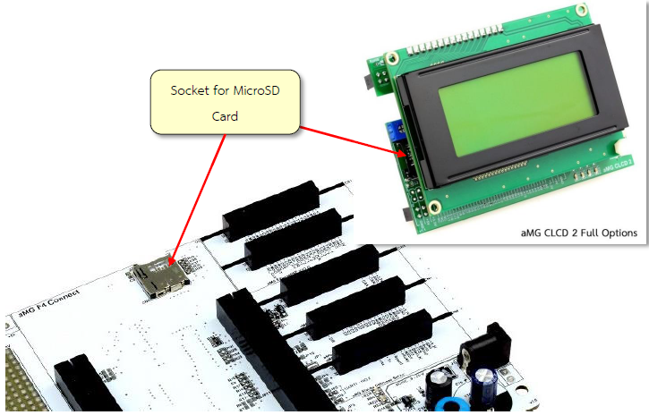
Figure 2-2: Sockets for MicroSD card
If the user has a separate SD card reader, then it can be connected to STM32F4DISCOVERY as shown in Figure 2-3.
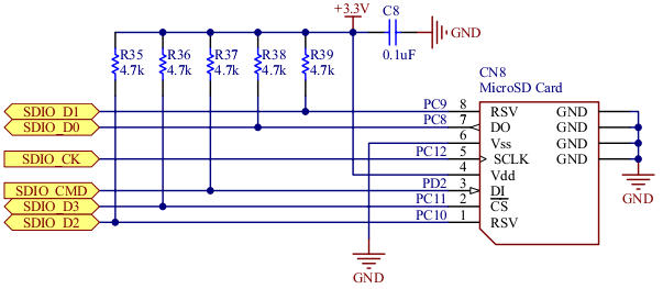
Figure 2-3: Circuit for connecting MicroSD card
Note that Waijung blockset is not compatible with SD card SPI model. Users can read and write to SD card module that works with SPI interface.
2.3 How to use Data Logger Block
In Simulink library >> Waijung Blockset >> STM32F4 target >> On Peripheral Chip >> SDIO contains blockset for recording on SD Card.

Figure 2-4: Characteristics and features of the Data Logger Block Ascii.
2.3.1 Cautions and Restrictions of use
- It is suitable for storage with low sampling rates (as recording is done every 0.5 seconds). If user wish to record at higher sampling rate, then high speed SD card should be used which will be introduced in the next chapter.
- Data logger block do non-stop recording. Users may use the Enable subsystem block to start or stop the recording.
- During the recording process, SD card can be removed but the final data may be lost.
2.4 Experimenting Data logger with Ascii.
Aim
- Enable the users to store data on SD card using Data Logger Block.
- Enable the users to browse through the SD card on a PC
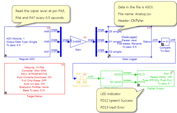
Figure 2-5: Simulink model for storing/writing the data in SD card
In this example, experiment will be conducted for logging the Ascii data logger which is actually a signal from pin PA5, PA6 and PA7 to the SD card. Sampling will be done every 0.5 second. Download the model into STM32F4DISCOVERY. The red light will flash (symbolizing error), if there is no SD card.
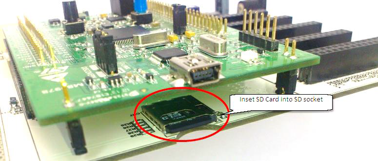
Figure 2-6: Insert SD card in the respective socket of aMG F4 connect board
When user inserts the SD card into the aMG F4 Connect or aMG CLCD2 (as shown in Figure 2-6) for recording the data on the SD card, the green LED starts flashing (symbolizing success). With the help of a computer or laptop, open the file as shown in Figure 2-7. A word of caution is, whenever the SD card is inserted or removed, the board should be powered off.
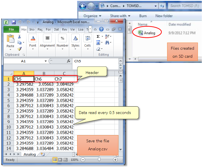
Figure 2-7: Recorded data from three pins and displaying it using Microsoft Excel
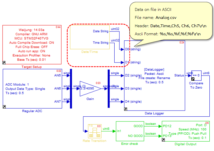
Figure 2-8: Simulink Model for real-time data recording on MicroSD card
Data / time Subsystem Block module is used to read the digital clock using I2C serial communication. Real-time readings are converted into String text format.
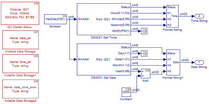
Figure 2-9: Subsystem Block module for reading the time from a digital clock
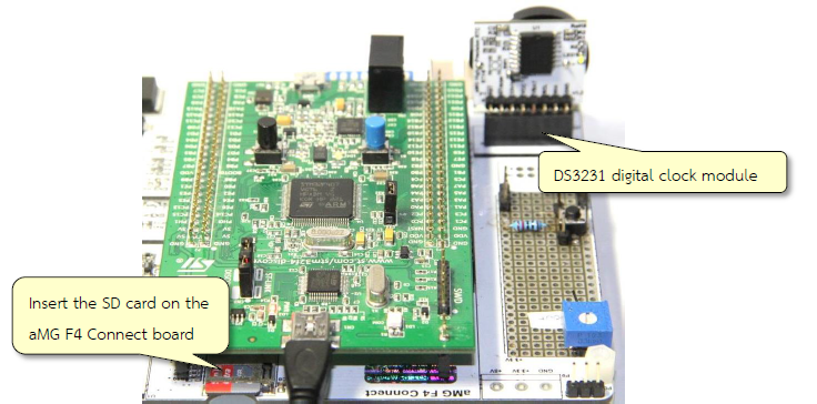
Figure 2-10: Devices used in the experiment are data on the SD card and digital clock module
When it comes to SD card, with the help of computer or laptop, browse the file and open it with Mircosoft Excel. File will be containing data similar to Figure 2-11.
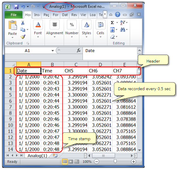
Figure 2-11: Information containing date, time and readings from the three channels
3 Experimenting with Data Logger in High Speed Mode
3.1 Introduction
High bandwidth storage applications such as signals from the brain or muscles or the application which requires higher sampling rate (greater than 1kHz) requires high speed mode of the data logger. For such purpose, the transmission of the SD card should be fast enough (class 4 or higher type of SD cards). Sometimes, the Ascii characters storage may not be suitable because the CPU requires more processing time.
So in the SDIO Waijung Blockset block has special support for high speed data writing on the SD card. The Ascii and the binary logging requires the installation of Notepad ++ so that the users can see the data in binary format.
3.1.1 Installing Notepad ++.
The information should be used as a Binary File Notepad ++. Users can Download and install it from http://notepad-plus-plus.org/download/v6.6.8.html HEX-Editor plugin, which includes the following steps.
After you install Notepad ++, select the Plugins >> Plugin Manager >> Show Plugin Manager and follow the Figure 3-1.
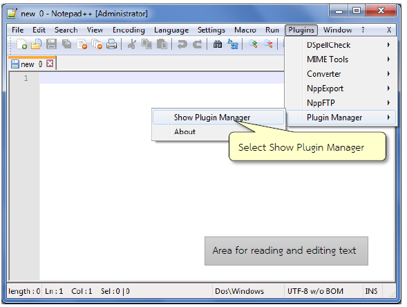
Figure 3-1: HEX-Editor plugin installed on windows Notepad ++.
Plugin Manager window will appear, select the first tab ‘Available’ and check HEX-Editor and click on install (computer must be connected to internet in order to install the plugin) and is shown in Figure 3-2.
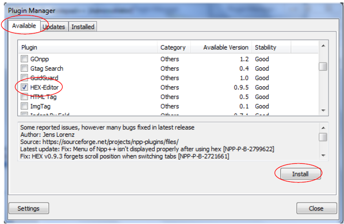
Figure 3-2: How to install the program HEX-Editor.Plguin of Notepad ++.
- After clicking on ‘Install’ installation will proceed and plugin will restart. Users can choose to use a Binary HEX-Editor for viewing it.
3.1.2 Using the Notepad ++ and HEX-Editor Plugin
- When opening the file in Notepad ++, binary data will appear as shown in Figure 3-3.
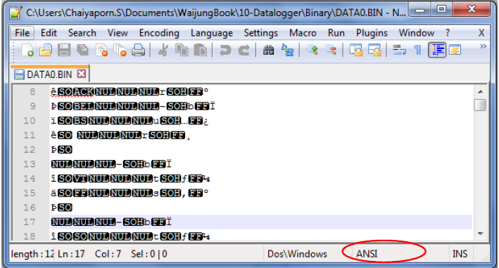
Figure 3-3: Binary data display in Notepad++
- Select Menu Plugins >> HEX-Editor >> view in HEX or press Ctrl + Alt + Shift + h. Data will then be displayed as hexadecimal format as shown in Figure 3-4 where each address will be of 8 bits (1 byte).
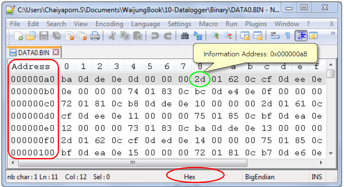
Figure 3-4: Binary data in Notepad ++ program with HEX-Editor plugin
3.2 How to use High Speed SD Card Write Block
In Simulink library >> Waijung Blockset >> STM32F4 target >> On Peripheral Chip >> SDIO contains blockset for recording data in a high-speed SD card. This includes indicator for SD card as well.
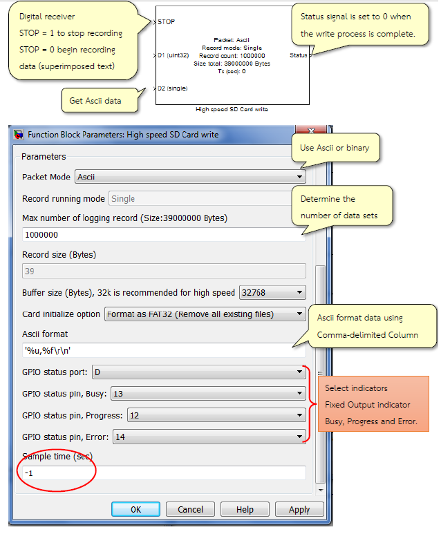
Figure 3-5: Characteristics and properties of a High Speed SD Card Block Ascii
3.2.1 When Data Collection will End?
- When space on the SD card exhausts;
- The all data sets are collected which have to be recorded;
- When the STOP pin input signal of High Speed SD Card Write Block is 1.
3.2.2 Limitations of Use
- High Speed SD Card Write Block is the only one Block Model.
- 250 MB space is reserved from SD card storage as there is much time error for storing first 250 MB
- The data is split into multiple files if the data is more than 3.99 GB
3.2.3 Considerations during Design Phase
Setup involves consideration of the following points.
- Data transmission speed of the SD card (for example 4MBytes/sec, 10MByte/sec or more).
- Size of Buffer (typically around 32k if you use more than that user must install SDRAM).
- Random write.
- Sample size for one.
Condition
- The size of the data to be saved must be less than the size of buffer.
- The writing speed must be less than the speed of data transmission of SD card.
For example, to calculate the speed of the SD card;
If user wish to save data that contains 32 bit counter, data received from ADC 2 channels will be of 8 bytes (4 byte + 2 byte + 2 byte) and use 50 microsecond per sample to save the data. So the data writing speed will be 8 bytes per 50 microseconds or 160000 bytes per second.
File size calculation
Let N be the number of data to be recorded, thus the size of the File = N × record size.
To calculate the amount of time required to save the data.
Let N be the number of data to be recorded, so the time needed to record (s) = N × sample time.
The indicator
- Busy LED indicator will be ON for the initial configuration of the Open Card Format and space for storage.
- Progress indicator LED will flash at a frequency of 5 Hz during recording and LED will be flashing at a frequency of 0.25 Hz when the recording is finished. The user can then remove the SD card.
- LED indicator for the error will be ON when there is an error during recording process.
Upon completion of the data recording, users can view the recording including the SD Card Error in the MSG.TXT.
SDIO has a block which deals with the saving of data to the SD card. Properties of Data logger and high speed SD card write are described in Table 3‑1.
Table 3-1: Difference between Data Logger with High speed SD card write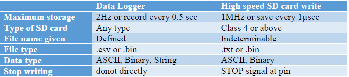
3.3 Data logger Experiment-ASCII High-Speed Mode
Aim
- The user can store the Ascii data into SD Card Data logger using the high speed mode;
- For a user to observe and understand the indicators during data storage;
- The user can calculate the time it takes to collect data.

Figure 3-6: Simulink model for storing data on SD card
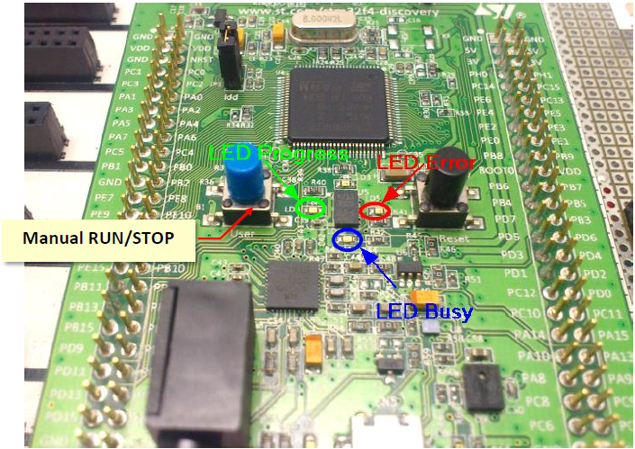
Figure 3-7: LED indicators on the SD card
After inserting the SD card into the respective socket, download the model into STM32F4DISCOVERY. Users can observe the LED indicators as shown in Figure 3-7.
- At the beginning of the data collection, indicator LED Busy (blue) is ON and blinks during the data collection stage. It takes around 10 sec to few minutes depending upon the size of data which needs to be recorded.
- During write process, the LED Progress (green) will blink at a frequency of 10 Hz (every 0.1 seconds)
- When the data write process is complete, the LED Progress (green) starts blinking at the frequency of 0.25 Hz (every 2 seconds). Now user can remove the SD card. From the socket.
Note the time it takes to collect data for this example (after Initialization) is about 60000 × 100e-6 = 6 seconds. - When user wish to see the data in the SD card, the SD card needs to be connected to a computer and then see file MSG.txt which contains the confirmation message of data logging, the recorded information and the sampling rate.
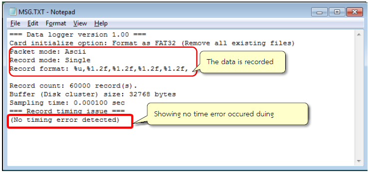
Figure 3-8: Message in MSG.TXT when writing/recording is finished
- Users can view the data saved in the File Name Data0.txt (User can set the File Name).
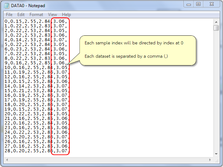
Figure 3-9: Data recorded in Data0.txt
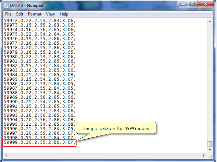
Figure 3-10: Data recorded in the last Data0.txt.
If the user removes the SD card before LED Progress (green) start blinking at 0.25 Hz then following message will be displayed (as shown in Figure 3-11).
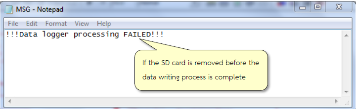
Figure 3-11: MSG.TXT messages in case of errors during data recording
3.4 Experimenting Binary Data logger for high-speed mode.
Aim
- Allow users to store data to SD Card Binary Data logger using the high speed mode.
- To help the user in understanding binary format for storage.
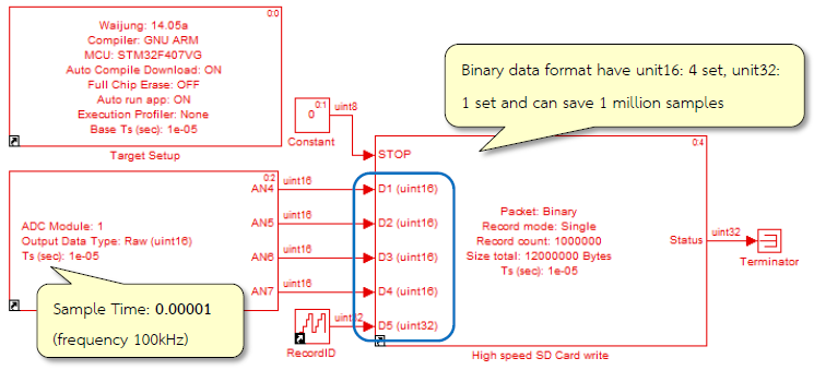
Figure 3-12: Simulink Model for saving binary data to SD Card at high speeds
After the user puts SD card in the socket, download the model into STM32F4DISCOERY, data can be viewed from MSG.txt. The recorded data can be seen from Figure 3-13. The data is written at a very high speed i.e. 1 million bits per second.
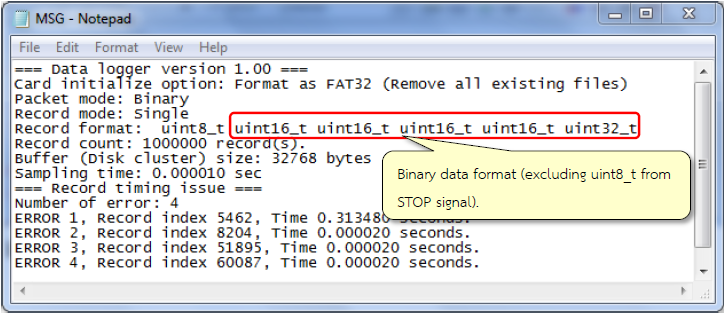
Figure 3-13: MSG.TXT contains binary text after writing process is complete
For reading the saved binary data, the user should use Notepad++ program at HEX Editor plugin as shown in Figure 3-14. Format of each set is a value which is obtained from 4 channels of ADC. Each channel has 16 bits or 2 bytes (so in total there are 8 bytes), 4 bytes are used for bit indexing and 4 bytes are used to identify dataset.
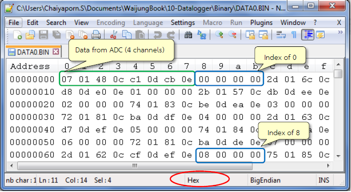
Figure 3-14: Format of binary data recorded in the first period
Users can observe the final data set recorded from the index 0x0F423F or 99,999,910 as shown in Figure 3-15.
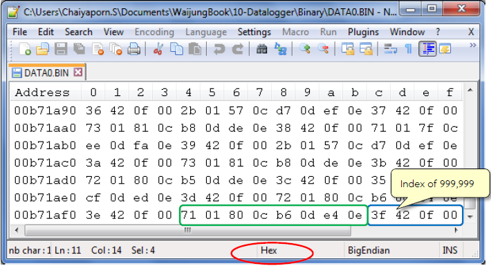
Figure 3-15: Final binary recorded data
In this example, the size of the file is:
N = 999,999 and the data size per sample = 12 bytes.
Therefore, the file size is equal to 12 x 999,999 = 119,999,988 bytes or 11.44 Mb.
Note 1 kB = 1024 Byte, 1MB = 10242 = 1,048,576 Byte.
3.5 Experiment to Abort Writing/Recording with Manual STOP
Aim
- The user can stop the recording by pressing the power button;
- The user can adjust the data which is to be recorded.
In case, user wants to stop data recording, user can send signal (data) for example external input signal from Digital Input Block to STOP port of High Speed SD Card Write Block.
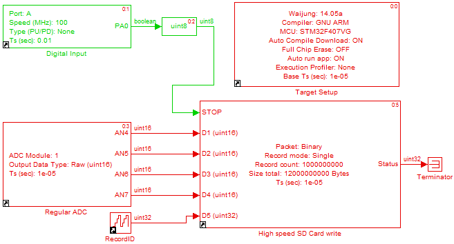
Figure 3-16: Simulink model for aborting the recording process on SD card with push button
After inserting the SD card into the socket, download the model into STM32F4DISCOVERY. It will start recording the data and the LED indicator (busy process) will flash at a frequency of 10 Hz. The user can press the blue button (which is actually pin PA0) to stop the recording process.
The LED indicator will start flashing at a rate of 0.25 Hz. The user can then remove the SD card. User can see the recorded data in the MSG.txt file and is shown in Figure 3-17.
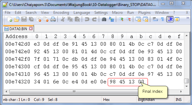
Figure 3-17: Results recorded after manual stop
This examples shows that the user cannot set certain dataset (because of switch pushing time). Figure 3-18 shows the index value from Counter Block (named RecordID) which is compared to the number of dataset that has been set. User can set many values by adjusting the DIP switch.
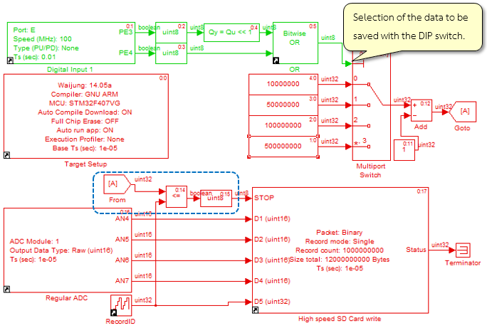
Figure 3-18: Simulink model for the data stored on the SD card when stop with DIP switch.
The position of the DIP switches will determine the length of the data which will be recorded from the dataset.
Table 3-2: Position of switch for specified number of data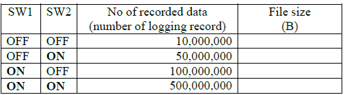
I feel that in Table 3-2 one set of 12 bytes predict the size of recorded data
4 Using MATLAB for Reading Binary Files
4.1 Introduction
Opening .bin file on Notepad++ may cause problem in program memory in case the size of the file is too big (>1GB). MATLAB can be used to open such big (.bin) files and can transform data to decimal number and arrange the data in matrix/array format. Now the data is ready for further processing such as graph plotting etc.
MATLAB has set of instructions in order to read data from the binary file and users can get more information from the following link in which data is read from DATA0.BIN file which has a size of 1.11 GB. The process is shown in Figure 4-1.
http://www.mathworks.com/help/matlab/low-level-file-i-o.html
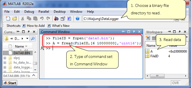
Figure 4-1: MATLAB window to set the instruction for reading .bin file
fopen command is used to open a binary file. fread is used to read the file which is open in the first line of the command. The parameters of the fread are the FileID and the way the file should be read i.e. (6, 10000000) and converts the data into unit16 data format and finally storing the information in a variable A. It is worth mentioning here that the way the file should be read must be the same the way the file in written in terms of type of information else the readings will be varied.
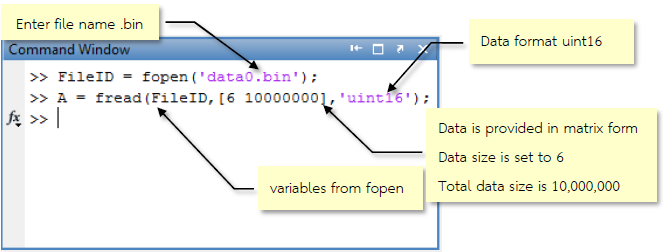
Figure 4-2: Description about fopen and fread functions
Data read form the command fread is stored in a variable A and MATLAB can be used for data graphical representation as in Figure 4-3.

Figure 4-3: Graphs from data read from ADC channel 4
4.2 Sample Applications
Aim
- Enable users to store data in binary format to SD Card Data logger using the high speed mode;
- Enable users to read and manipulate data in Binary format with a MATLAB program.
Download the model as shown in Figure 4-4 on STM32F4DISCOVERY board. The model will take readings from the ADC module channels 4 to 7 every 10 msec. The readings obtained from channel 4 and 5 will be converted to hexadecimal or raw data in voltage and the readings obtained from channel 6 and 7 will be saved as raw data.
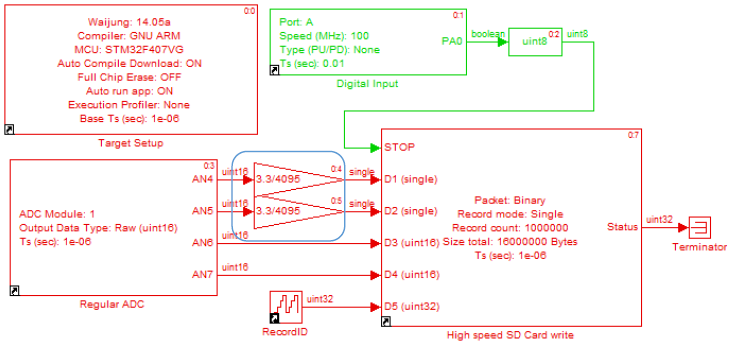
Figure 4-4: Simulink model for storing binary data in various formats
When it reaches 1,000,000 (which is the total size of the data), the user can remove the SD card from socket and can observe the results as in Figure 4-5 using Notepad ++.
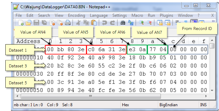
Figure 4-5: Recorded results
One dataset contains the values read from AN4 and AN5 (4 bytes data saved as single), AN6 and AN7 (2 byte data saved as unit16) and value from RecordID block (4 bytes saved as unit32).
Since one dataset contains different data types (single, unit16, unit32), Figure 4-6 shows the MATLAB instructions to read file from .bin file stored as different data type and save them to variables AN4, AN5, AN6 and AN7 for which are basically the magnitudes of voltage of channel 4, 5, 6, and 7 respectively.
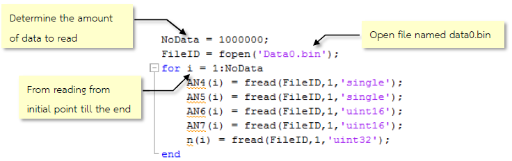
Figure 4-6: Set of instructions for reading data from a .bin file
When the user will type the following lines of command, the graphs will be plotted for each ADC channel (from 4 to 7) between data read and time.
subplot(2,2,1),plot(n*1e-6, AN4),grid <Press Enter>
subplot(2,2,2),plot(n*1e-6, AN5),grid <Press Enter>
subplot(2,2,3),plot(n*1e-6, AN6),grid <Press Enter>
subplot(2,2,4),plot(n*1e-6, AN7),grid <Press Enter>
These MATLAB commands will show the graphs of the deta read from various ADC channels and they are shown in Figure 4-7.
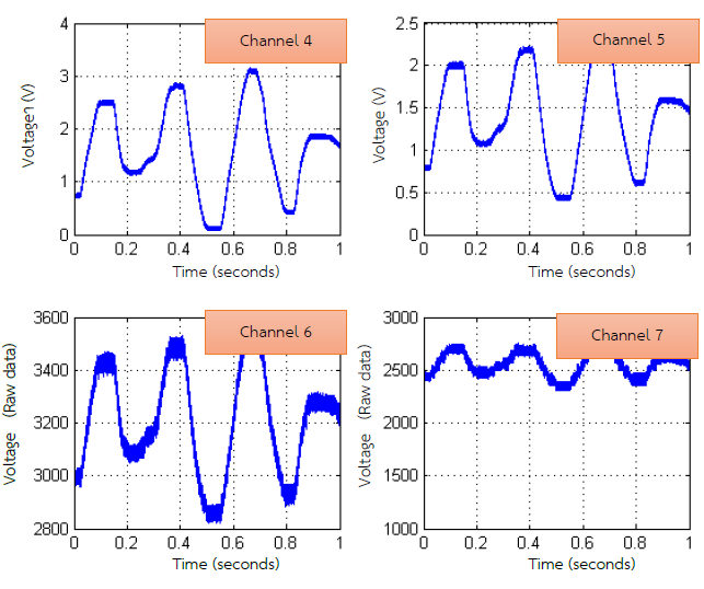
Figure 4-7: Graphs of the data read from ADC channels 4 to 7
5 References
- STMicroelectronics, “STM32 F407xx Datasheet-production data [Online],” 2013.
- STMicroelectronics, “User manual: STM32 ST-LINK Utility software description [Online],” 2014.
- Wikipedia, “Secure Digital,” [Online]. Available: http://en.wikipedia.org/wiki/Secure_Digital.STMicroelectronics, “RM0090: STM32F40xxx Reference Manual [Online],” 2013.
- http://www.amazon.com/gp/feature.html?ie=UTF8&docId=1000633771
- Wisco Industrial Instruments, “Data Logger Technical Knowledge,” 2013. [Online]. Available: http://www.wisco.co.th/main/sites/default/files/articles/Logger_Knowledge_0.pdf
- http://www.mathworks.com/help/matlab/low-level-file-i-o.html
- http://notepad-plus-plus.org