How to Use I2C Communication Port
download all demo files: I2C.7z
1 I2C Communication Port
1.1 Introduction to I2C
I2C stands for Inter-Integrated Circuit invented by Philip semiconductor now days known as NXP semiconductor. I2C is intended for low-speed data transfer between devices such as assessing low speed ADC and DAC, reading real time clock etc. The EEPROM memory as an I2C communication feature is connected to the system bus and transfers data between the devices. Using only two signal lines as shown in Figure 1-1, which can reduce the number of cables and accessories. It is popular in small embedded systems.
I2C communication uses digital transmission. A bidirectional open-drain line which can transfer data in line with 2 sets of Serial Data Line (SDA) and is responsible for sending the data and Serial Clock Line (SCL) that transmits the clock signal. The speed of data transfer depends on the frequency of the clock (SCL) of STM32F4 (100 kHz bus frequency is considered as standard frequency and 400 kHz is considered fast) [1, p. 575].

Figure 1-1: Connecting an I2C device [2, p. 1]
The signal of the device is open-drain voltage, which is equal to GND (logic zero) and for high impedance the logic is one. Hence there is a need for pull-up resistors and external power supply VDD (3.3V or 5V).
Figure 1‑1 shows an example of connecting devices to the I2C bus. In the figure, we can see that there is one Master (for transferring the data) and three Slaves (to receive the data). Master specifies the command that you want to read information (Read) or send information (Write) to the Slave device. Device identification of the Slave in needed for communication which is established by using a 7-bit or 10-bit address and is set by the manufacturer. Information about the address is listed in the datasheet of the device and can be defined either in software or hardware.
Figure 1‑2 shows the communication pattern and data transmission process. Details are mentioned below.
- To start the communication status, I2C Master device sends the START command, which makes all the Slave device ready to receive data from the bus data line (SDA).
- Master device sends the 7-bit address command followed by a read or write (Read / Write) a 1 bit.
- Information on the Slave bus will be read and determine whether or not they match the address of the corresponding 1 bit address and sends an ACK back to the Master and prepare to proceed.
- Data transmission between Master and specified Slave address is performed continuously in case the Master Slave devices send commands to Read a series of data sets of 8 bits (1 byte) when the Master device receives ACK signal upon receipt of each byte.
- Master device sends STOP command to end the communication I2C.

Figure 1‑2: I2C communication pattern
Figure 1‑3 shows an example of reading the temperature measured by the humidity sensor (HIH6130). Data is of 2 bytes.
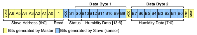
Figure 1‑3: Sample reading measured by humidity sensor
1.2 How to Use I2C Blockset
Waijung I2C Blockset includes I2C Master Setup Block which is shown in Figure 1‑4. User need to select 3 pins i.e. SDA, SCL and the frequency.

Figure 1‑4: Characteristics and user settings for I2C Master Setup Block
I2C Master Read/Write Block is shown in Figure 1‑4 have functions to receive or send data to Slave device with I2C using STM32F4DISCOVERY as Master device. User can set 7 bit Address of Slave device that want to communicate via I2C.
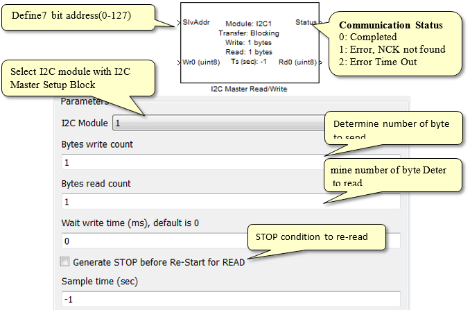
Figure 1‑5: Characteristics and settings for I2C Master Read/Write Blockset
2 Using Humidity/Temperature Sensor HIH6163
2.1 Equipment Used
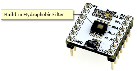
Figure 2‑1: aMG Humidity/Temperature sensor
Figure 2‑1 shows the board measuring humidity / temperature. Install the sensor HIH6131-021-001 from Honeywell, which has the following features.
- Communication via I2C.
- Accuracy of relative humidity measurement: +/- 4% RH.
- During the measurement of relative humidity: 10 – 90% RH.
- The accuracy of the temperature measurement +/- 1 ° C in the sandstone.
- Temperature range: 5-50 ° C in the sandstone.
- 14-bit data resolution.
Alarm feature: This provides the ability to monitor whether the RH level has exceeded or fallen below predetermined and critical levels within the application. (See the work [4]).
When users want to read both the humidity and temperature, sensor must submit a Request to Address in the specified format as shown in Figure 2‑2.
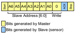
Figure 2-2: Shows an I2C communication for humidity and temperature readings [2, p. 1]
After that, the Master device starts reading from the sensor and read data is of 4 bytes (32 bits), which includes the status of the sensor (2-bits), humidity (14-bits) and temperature (14-bits).
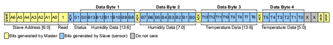
Figure 2-3: : I2C communication for humidity and temperature sensor [2, p. 2]
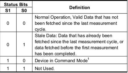
Figure 2-4: Sensor status
Digital Readout can be converted to units% RH and Celsius. According to the following equation:
Humidity (%RH) = 14bit_HumidityData x 100 / (2 14 -2)...........................................(1)
Temperature (◦C) = [14bit_TemperatureData x 165 / (2 14 -2)] – 40........................ (2)
Figure 2‑5 shows the aMG Sense Humidity / Temperature board with aMG F4 Connect. Furthermore connection with power supply, SCL, SDA and GND are also highlighted. The user must select the I2C module 1 and address. The active SDA pin is PB7 and for SCL is PB8.
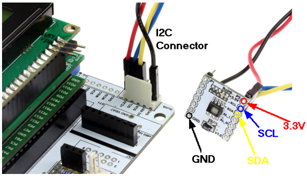
Figure 2-5: Connections between aMG Sense Humidity / Temperature with aMG F4 Connect
2.2 Measurement of Humidity and Temperature Content
Purpose
- In order to enable the students to understand I2C communication;
- The users can read the humidity and temperature of the HIH6131.
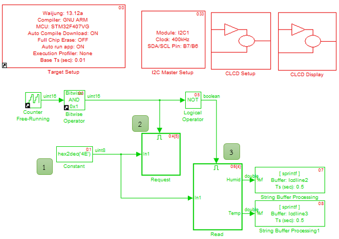
Figure 2-6: Simulink Model for humidity and temperature through I2C communication
Figure 2-6 shows the Simulink model for reading the humidity and temperature from HIH6131 sensor through an I2C communication and display the results to LCD. The description of work is as follows:
- Configure S7-bit slave address of HIH6131 [2, p. 1] which is 0x27 or 0100111, when combined with a bit Read / Write to “01001110” or 0x4E.
- Figure 2 2 can be written as a title Enable Subsystem block of request as shown in Figure 2 7 which provides a Master Address and write command Write (value 0x4E).
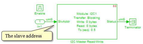
Figure 2-7: Enable subsystem block of request
- When request is made, then the subsystem will read as in Figure 2 8 and it will start reading data from sensor until all 4 bytes are received. Next step is Logic and Bit operation to separate the data to sensor status (2 bit), relative humidity (14 bit) and temperature (14 bit)
The display data (that has to be converted to) relative humidity and temperature which has been mentioned in equation above is shown via LCD display.
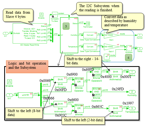
Figure 2-8: Enable Subsystem Model for readings from sensor and operation of Binary Operation
Experimental results show the relative humidity and temperature readings from sensors HIH6131 communication through I2C and LCD display updates the display every 0.5 seconds.
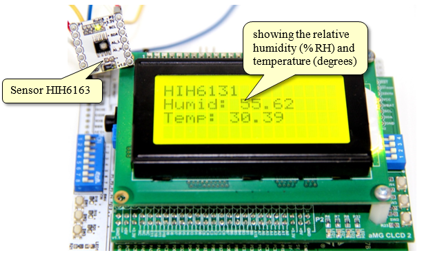
Figure 2-9: Experimental results of humidity and temperature readings from sensors HIH6163
Waijung Blockset version 13.12a has a block to read data from HIH6131 sensor in Simulink library: Waijung Blockset >> Hardware Modules>> aMG Sense Temp Humid. Figure 2 10 shows an example of using HIH6131 block. User have to put I2C Master Block on main model. Data which is received from HIH6131 are relative humidity and temperature. User can immediately use them to display or record data.

Figure 2-10: Simulink Model for humidity and temperature readings using HIH6131 block
3 Using Pressure Sensor MPL3115A2
3.1 Equipment Used for Experiment

Figure 3-1: aMG Sense Pressure / Altitude board
- 95 V to 3.6 V Supply Voltage, internally regulated by LDO
- 6 V to 3.6 V Digital Interface Supply Voltage
- Fully compensated internally
- Direct reading compensated
- Pressure: 20-bit measurement (Pascals)
- Altitude: 20-bit measurement (meters)
- Temperature: 12-bit measurement (degrees Celsius). The MPL3115A2 is offered in a 5 mm x 3 mm x 1.1 mm LGA package and specified for operation from -40 °C to 85 °C.
- Autonomous data acquisition
- Resolution down to 0.1 m
- 32-Sample FIFO
- Ability to log data up to 12 days using the FIFO
- 1 second to 9 hour data acquisition rate
- I2C digital output interface (operates up to 400 kHz)
Value of Slave address, 7 bit Address of MPL31152A, is 0x60 [5, p. 6] or ‘1100000’ when combined with Read/Write bit the binary will be ‘11000000’ or 0xC0
Flow chart of using and reading data as polling is shown in Fig [5, p. 12] . Read data as air pressure to use as Barometer [5, p. 32]

Figure 3-2: Flow chart for settings the sensor
Pressure and temperature data can be converted digitally to the air pressure in Pascal and the temperature in degrees Celsius. The next experiment describes this phenomena.
3.2 Measurement of air pressure.
Purpose
- In order to enable users to understand the I2C bus communication (read / write data by address of the device’s internal registers Slave).
- The user can read the air pressure from the MPL3115A2.

Figure 3-3: Simulink model for reading air pressure and communicates through I2C
Figure 3-3 shows the Simulink model for the reading of the air pressure using MPL3115A2 sensor and communicates through an I2C and displays the results on a LCD screen. In this example, we will read the air pressure and the reading of the Polling which have to start from the default settings by subsystem block which is shown in Figure 3-4.
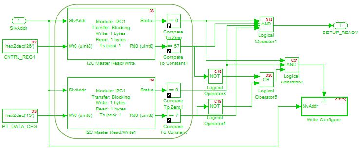
Figure 3-4: Subsystem model for the initial setup of the sensor MPL3115A2
Subsystem in Figure 3‑4 will check that MPL3115A2 has set the values as in Figure 3‑2 or not. Register 0x26 of sensor must be equal to 0x39 and register 0x13 must be equal to 0x07. If the setting is correct, the ON signal will be sent to start reading and if not correct then follow as shown in Figure 3‑5.
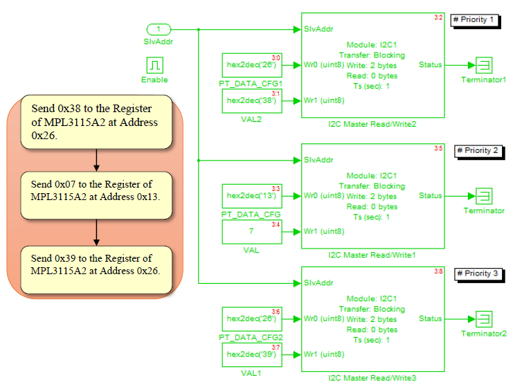
Figure 3-5: Subsystem Model for initial configuration MPL3115A2 Sensor with I2C Master Write
When completed, the sensor began to read the air pressure and temperature which are identified in Figure 3‑6. Address of the registers of the sensor (in the registers address 0x00) to read the air pressure and temperature which are 3-byte, 2 bytes, respectively.
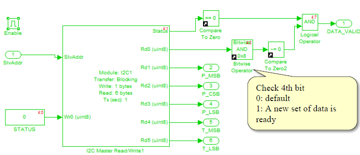
Figure 3-6: Enable Subsystem Model for reading data from sensors MPL3115A2
When status of sensor has data which is not ready to be sent (DATA_VALID = 1), value of air pressure will be in digital data (20 bit unsigned). Data’s (always positive) first 18 bits will come from P_LSB and last 2 bit in position 5-4 of P_LSB showing decimal value [5, p. 23]. All data will be converted into pressure value in Pascal by Convert Subsystem Block that shown in Figure 3‑7. Figure 3‑8 shown example of Convert Subsystem Block.
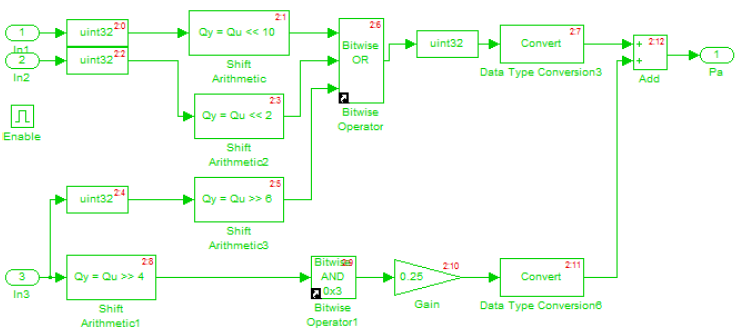
Figure 3-7: Enable Subsystem Block for converting pressure units from digital form into Pascal
In order to display temperature data from MPL31152A user have to create Subsystem Model for convert read data in digital data to 12 bit data in 2’s complement. First 8 bits come from T_MSB and last 4 bits in 7-4 of T_LSB for display decimal value.
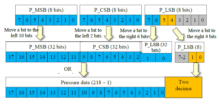
Figure 3‑8: Example to convert Subsystem Block
Figure 3‑9 shows experimental results showing the air pressure readings from sensors MPL3115A2 communication through I2C and then displayed through the LCD.
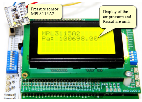
Figure 3‑9: The results of the pressure sensor readings MPL3115A2 communication through I2C
If the user wants to read the height above sea level (Altitude), this can be done by setting up a working sensor MPL3115A2 as an Altimeter Model (registers 0x26 sensor be equal 0xB9) then create Subsystem model for conversion. The height above sea level readings are in the form of digital data. Data is a 20-bit 2’s complement (positive and negative), the first 16-bit data from the P_MSB and P_CSB bit of P_LSB 7-4 showing the decimal places (resolution 0.0625 m) [5, p. 23].
In Waijung Blockset version 13.12a, block for reading data from MPL3115A2 sensor is available in the Simulink library: Waijung Blockset >> Hardware Modules >> aMG Sense Pressure. Figure 3-10 shows an example of using MPL3115A2 block. Users must place the I2C Master Block Model. Primary data from MPL3115A2 block is the air pressure. The information can then be used to display or record it immediately.
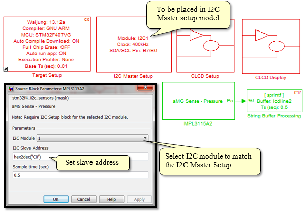
Figure 3‑10: Simulink Model for checking the air pressure using MPL3115A2 Block
4 Using light sensor MAX44009
4.1 Equipment Used in this Experiment
In this section, an example is demonstrated for intensity of light from LDR sensor using analog signal [6]. The resistance of LDR sensor will vary in accordance with the variation in the light intensity. However LDR sensor is not suitable to measure light intensity because conversion of voltage to light intensity unit (LUX) is dependent on the electric voltage and resistance which are affected by external temperature.
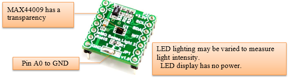
Figure 4‑1: aMG Sense Light2
Figure 4‑1 shows aMG Sense Light2 board for photometric and sent over the I2C sensors from MAX44009 (Manufacturer: Maxis Integrated). This board has the following features.
- The sensor is small, 2mm x 2mm x 0.6mm;
- Power supply 1.7V to 3.6V at a current of 0.65 uA;
- The intensity of illumination: 0.045 Lux to 188,000 Lux.
User can select Slave address of MAX44009 by connecting supply voltage )VDD) or Ground (GND) at pin A0 (Pin3) of MAX44009 when connected to supply voltage (address is 0x96) or Ground (Address is 0x94) respectively.
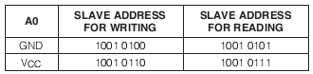
Figure 4‑2: Map of Slave address MAX44009 [7, p. 16]
To read data from sensors, users must read from I2C by address of the Register within MAX44009. Figure 4‑3 shows that the intensity of light measured in digital format in Address 0x03 and 0x04 with an exponent of Exponential [E3-E0] and the Mantissa [M7-M0]. Light intensity in Lux can be obtained from the following equations.
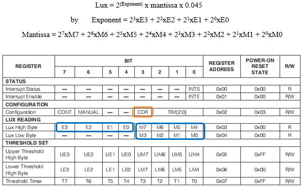
Figure 4‑3: Diagram of the MAX44009 register address [7, p. 7]
4.2 Reading the photometric MAX44009.
Purpose
- To allow the users to read the light intensity of the MAX44009
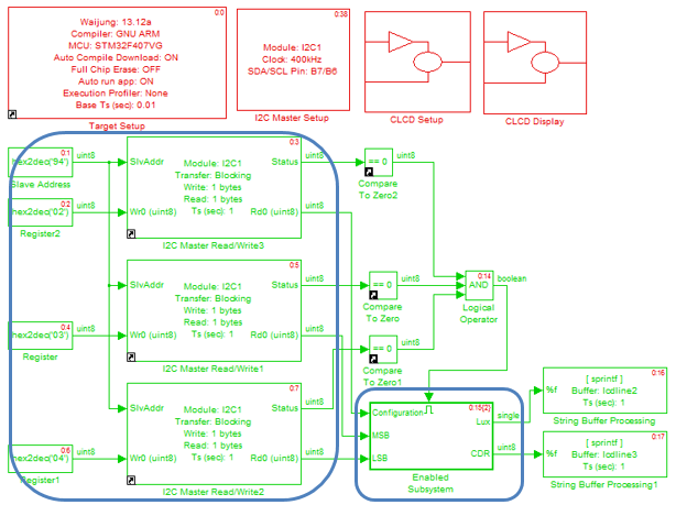
Figure 4‑4: Simulink Model for photometric readings and communication through I2C
After downloading the model into STM32F4Discovery, light intensity reading will start at the address of register of sensor we want to read. By start reading at value of sensor at register address 0x02 the readings of light intensity value (2 bytes) will be in register address 0x03 and 0x04 respectively.
Then convert data into “Lux” unit by Subsystem Model as Figure 4‑5. Since Simulink Block for power calculation cannot work with GNU compiler so user should use custom code block or MATLAB function Block. This example use MATLAB Function Block in Simulink library: Simulink >> User-Defined Functions.
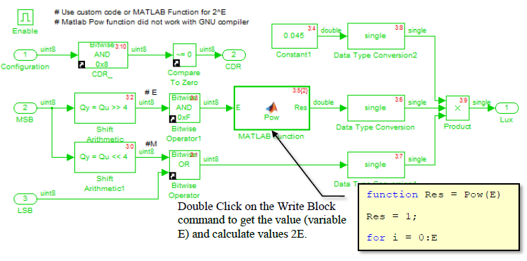
Figure 4‑5: Subsystem for converting digital data into a unit Lux
Figure 4‑6 shows experimental result of the experiment in which the intensity of the light is measured using MAX44009 sensor by reading every 1 second. Reading of light intensity is increased when the light is very bright (up to 188,000 Lux when it gets direct sunlight).

Figure 4‑6: Results of photometric readings from the sensor MAX44009
In Waijung Blockset version 13.12a, reading data from MAX44009 block can be done via Simulink library >> Waijung Blockset >> Hardware Modules >> aMG Sense Light. Figure 4-7 shows an example of using the MAX44009 Block. User must place I2C Master Block Model. Users can use this module for displaying and recording the information immediately.

Figure 4‑7: Simulink Model for reading the light intensity using MAX44009 Block
5 Using Digital Clock Module DS3231
Time is money. Human life is dependent on time. We set our schedule for everyday life to match with the present life demands. So we can say that human life style is associated with time. There are many units of time by volume. The smallest unit of time is second and 60 seconds makes a minute. 60 minutes makes an hour and 24 hours makes one day which defines our life routine. 30 or 31 days makes a month and 12 months constitutes a year. These all definitions are related with the rotation of the Earth around the Sun.
The SI definition of second is “the duration of 9192631770 periods of the radiation corresponding to the transition between the two hyperfine levels of ground state of the Caesium 133 atom”. In embedded system, crystals are used to create a defined frequency signal with a fixed frequency. For example, in the CPU or computers and microcontrollers, timing is determined by crystal circuit which gives a very precise frequency and is less affected by outside temperature.
Time is necessary in personal computer system especially in data storage that has to keep date, month, year. Time reference can be used in small embedded system too, for the example: store data from sensors with date, month, and year, or setting a timer to on and off automatic devices.
5.1 Equipment Used in this Experiment

Figure 5‑1: aMG high precision RTC
Figure 5‑1 shows the display board aMG High Precision RTC DS3231 from Maxim Integrated Raid which is a digital clock module. The module has a crystal inside having a signal frequency of 32kHz, which is used to count the seconds, minutes, hours, days, months and years of a calendar in order to adjust the date, the leap year (1 year = 366 days) till the year 2100. [8, p. 1]. All data is sent via the I2C communication module which can be connected to a battery backup to maintain the time no matter power of microcontroller goes off.
Slave device address of the IC DS3231 is 0xD0 [8, p. 17]. To read a clock and calendar, users must read that from the specified I2C address register of the DS3231 as shown in Figure 5‑2. Address of 0x00 to 0x06 is to keep the clock and the date correct. The data format is Binary-coded Decimal (BCD).
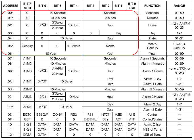
Figure 5‑2: Memory map of digital clock module [8, p. 11]
5.2 Time Setting Clock Module DS3231
In Simulink Library >> Waijung Blockset >> Hardware Modules >> aMG High Precision RTC Block for DS3231 through I2C interface consists of the following.
5.2.1 How to use DS3231 Configure Block
After putting the battery back-up or start the DS3231 clock for the first time, the calendar data and time is will be shown as 01/01/00 00:00:00 (day / month / year. Hours: minutes: seconds), so it is necessary to set the clock. DS3231 Configure Block is Subsystem Block included in DS3231 Blockset so that the user can set the time by pressing buttons (Digital).

Figure 5‑3: DS3231 configure block
Input port of the DS3231 Configure Block has the following functionalities.
- Port SlvAddr to the DS3231 Slave Address which is set to 0xD0.
- Port (+) UP to receive digital signals from the keypad. To increase the value +1
- Port (-) DOWN receive digital signals from the keypad. To decrease the value -1
- Port (*) MODE, the digital signal from the keypad. To select the operating mode, set the clock. Digital Debounce takes about 3 seconds to change the mode of operation. The port’s output of DS3231 Configure Block has the following functionalities.
- Port status displays the status of the clock setting as follows.
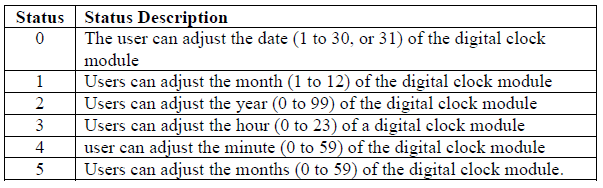
- Port Enable is to indicate the status of the clock and the clock button can be turned on – off for about 3 seconds on a digital signal.
5.2.2 Sample Time Setting Clock Module DS3231
Purpose
- To allow the users to set the default module DS3231 as a digital clock.
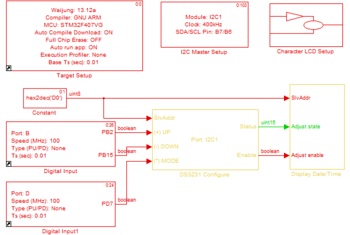
Figure 5‑4: Simulink Model for the initial setup of the module clock DS3231
Download model on the microcontroller and setup procedure is as follows.
- When the download is complete, the first-line LCD display shows the date and the second line shows current time;
- To set the time, press the Mode (SW3) and hold for 3 seconds. The LCD display will flash when the clock setting mode is ready for adjustment.
- Press the UP (SW1) or DOWN (SW2) to increase or decrease.
- Press the Mode (SW3) again to select the setting you want to adjust. By changing the position of the sequence (LCD will change for flashing) Date -> Month -> Year -> hours -> minutes and seconds.
- To exit configuration mode, press the Mode (SW3) and hold for 3 seconds again until no number is flashing on the LCD display and it shows the clock settings.
5.3 View the time, day, month, year of a digital clock module DS3231.
Purpose
- To allow the user to read the time and date of the module clock DS3231;
- To enable the user to use of a digital clock module DS3231.
5.3.1 How to use DS3231 Get Date / Get Time Block.
When users put the battery back-up and set the digital time clock module, users can read the time and date of DS3232 Get Time and DS3232 Get Date respectively. Figure 5‑5 shows Blockset for reading the time and date of the DS3232 which communicates through I2C so the user must place the I2C Master Block.
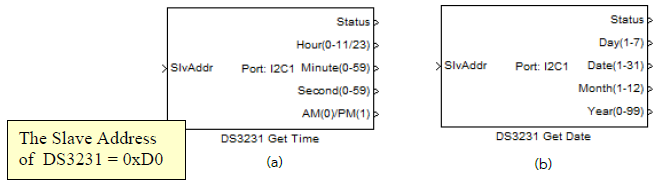
Figure 5‑5: (a) DS3231 Get Time Block, (b) DS3231 Get Date Block
DS3231 Get Time Block display the time read from the DS3231 digital clock module and the characteristics are as follows.
- Status indicator of reading I2C.
- Hour meter display units are in the range of 0 to 11 (AM / PM) or 0 to 23 (24 hours).
- Minute displays the value is in the range of 0 to 59.
- Second displays the value is in the range of 0 to 59.
- AM / PM display the time value i.e. 0 means the AM and 1 means the PM.
DS3231 Get Date Block displays the date on the calendar to read from DS3231 digital clock module are as follows.
- Status indicator of reading I2C.
- Day display units in the range of 1 to 7, in which the user can set the display till it’s Friday.
- Date is shown in the range of 1 to 31 depending upon the reader.
- Month shows the value in the range of 1 to 12, users can apply the results from January to December.
- Year of the display unit is in the range of 0 to 99.
5.3.2 Example of Reading the Time, Day, Month, Year of a Digital Clock Modules
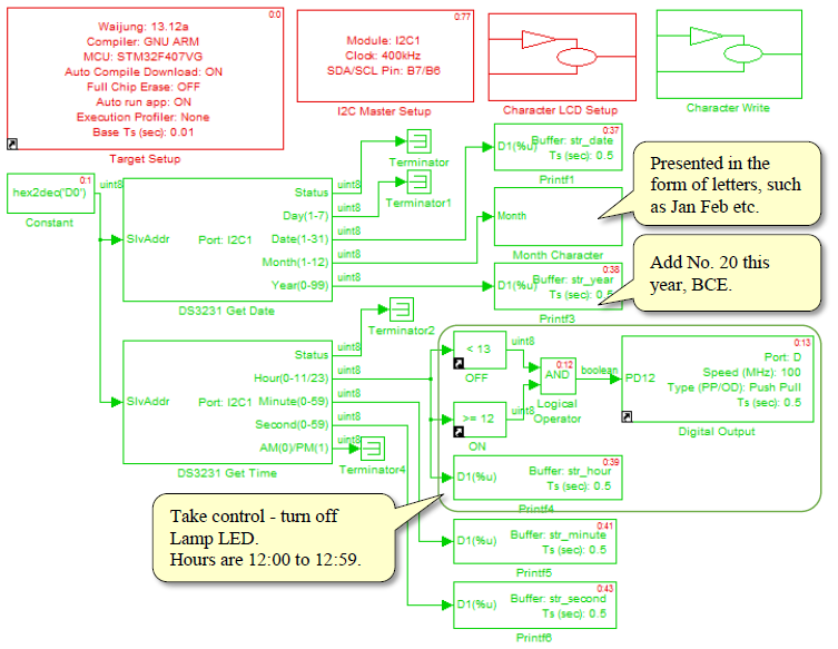
Figure 5‑6: Time for reading date from the module clock
Figure 5‑6 shown Simulink Model to read time and date from digital clock module by adding controlling part to ON-OFF external device by clock and change displayed date format.
After downloading the model into microcontroller, LCD shows calendar by Month. Character Subsystem Block in Figure 5‑7 will get month value and display in English format. Ex: data read from Month = 2, display will show it as Feb.
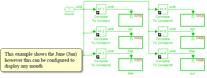
Figure 5‑7: Subsystem for displaying the month in English
Furthermore, user can apply DS3231 to use as Timer to ON/OFF external device. For example, when reading Hour, if the value is in between 12 and 13, digital output signal at PD12 will be ON so the LED1 will be on at 12:00:00 to 12:59:59 as shown in Figure 5‑8.
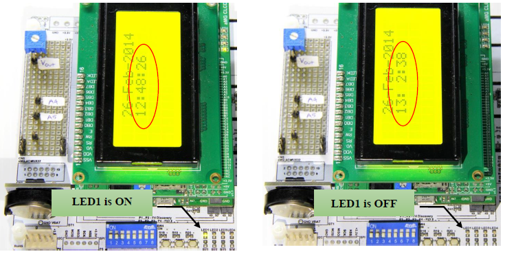
Figure 5‑8: Results – Reading the DS3231 clock, clock module and LED ON-OFF
5.4 Setting the Date and Time for Clock Module DS3231.
Purpose
- The user can set up a time and date for the DS3231 is a digital clock module;
- For a user to be able to apply to the clock to the DS3231 via the UART.
5.4.1 How to use DS3231 Set Date / Set Time Block.
When setting the digital time clock module, users can set the time and date on DS3232 Set Time and DS3232 Set Date Block respectively. Figure 5 9 shows Blockset to set the time and date of the DS3231 and it communicates through I2C. The input for DS3232 is Slave address, hour, minute and second and for DS3231 Set Date Block the input is Slave address, Date, Month, Year.

Figure 5‑9: (a) DS3231 Set Time Block, (b) DS3231 Set Date Block
Following are the attributes of DS3231 Set Time Block. and Set Date Block.
- Hour – Configured in the range of 0 to 11 (AM / PM) or 0 to 23 (24 hours).
- Minute – Configured in the range of 0 to 59.
- Second – Configured in the range of 0 to 59.
Following are the attributes of DS3231 Set Date Block.
- Date – Configured in the range of 1 to 31.
- Month – Configured in the range of 1 to 12.
- Year – Configured in the range of 0 to 99.
5.4.2 Example of Setting the Date of Communication through UART.
For this experiment users should pursue peripheral control via serial communication.
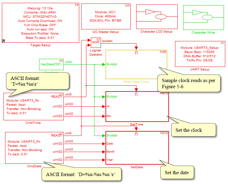
Figure 5‑10: Simulink Model for setting time and date of DS3231 via UART communication
Download Simulink model as shown in Figure 5‑10 into the microcontroller. The LCD display will show the time and date which is read from the DS3231 module. To set the clock, user must type respective commands on programs like TeraTerm or Putty terminal window like T = hours: minutes and then press Enter to Activate Subsystem in Figure 5‑11. An acknowledgement message of Ok will be sent and the clock settings will be complete and the LCD display will be showing the updated time.
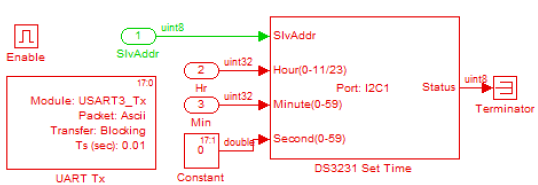
Figure 5‑11: Subsystem model for clock setting
To set the calendar, users need to type the command D = Date – Month – Year, and then press Enter to Activate Subsystem as in Figure 5‑12 which is a Subsystem Model for the calendar. Ok acknowledgment signal will be sent and setting of calendar will be complete. LCD will now be showing the data.
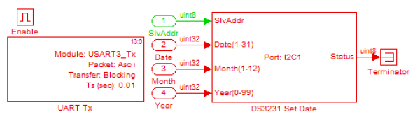
Figure 5‑12: Subsystem model for the calendar
Figure 5‑13 shows the equipment used in this study. Computer is connected to the aMG USB Converter-N Adapter. If not battery backed clock module is available then the LCD display will show the date as 1 January 2000 and start the clock at 0:00.
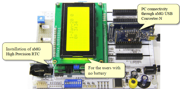
Figure 5‑13: Experiment for clock setting via computer
Figure 5‑14 shows the clock setting. After typing the command in Teraterm program, the program will communicate with the computer via serial port. Users can set the clock or calendar. When the clock is set, seconds start counting from 0 every time.

Figure 5‑14: Results of clock setting through UART communication
5.5 Reading Temperature from DS3231 Module
Purpose
- To allow users to read a digital clock temperature from DS3231 module.
Digital clock DS3231 module have a temperature sensor installed inside to reduce the error caused by temperature to external crystal circuit. As a result, the clock signal is the most accurate for temperature measurement. Figure 5‑15 shows DS3231 using DS3231Temperature Block, located in the Simulink Library >> Waijung Blockset >> Hardware Modules >> aMG High Precision RTC.
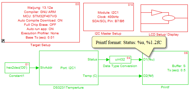
Figure 5‑15: Simulink model for the temperature reading from DS3231 and it communicates through I2C
Download model into the microcontroller and LCD display will show the temperature measurement. The precision of the reading is +/- 3 ° C [8, p. 1].
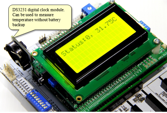
Figure 5‑16: Results from measuring the temperature using DS3231 (communicates through I2C)
6 Example of I2C Device to Bus
Objective:
- User can connect and read data from I2C devices that is connected as BUS
This example introduces the use of sensor for measuring humidity, temperature air pressure and light intensity at the same time by connecting SCL and SDA of the aMG board (Sense Humidity/Temperature, aMG Sense Pressure/Altitude and aMG Sense Light)2 in Bus is shown as Figure 6‑1.
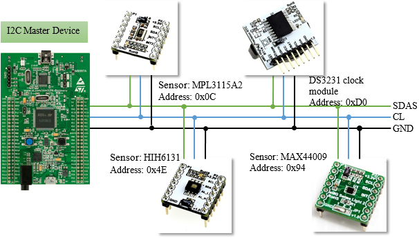
Figure 6‑1: Connection kit for detection of humidity, temperature, air pressure and light intensity
Figure 6‑2 shows a Simulink model for measuring temperature, humidity, air pressure and light intensity. Communication is using I2C and LCD screen displays time and date. Digital clock DS3231 modules are connected on the aMG F4 Connect board. The time and date information will be updated every 0.5 seconds.
- HIH6131 block for measuring humidity and temperature.
- MPL3115A2 block for measuring air pressure.
- MAX44009 block for measuring light intensity.
- DS3231 Get Time and DS3231 Get Date Block read time and calendar.
If one sensor is pulled off, LCD still display latest read value of that sensor and model still reads value from sensor.
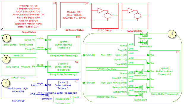
Figure 6‑2: Simulink Model for measuring temperature, humidity, air pressure and light intensity
Figure 6‑3 shows the experimental measurements from sensors connected to the system bus. As discussed in Figure 6‑1, when connecting the power supply and 3.3V to SCL SDA GND pin of aMG F4 Connect to the sensor, the data (temperature, humidity, air pressure and light intensity) will be displayed on the LCD display and it will be updated every 0.5 seconds.
When installing the digital clock module (DS3231) that was to set clock value on aMGF4 Connect, first line of LCD will show present date and time.
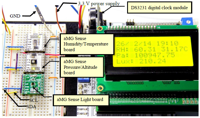
Figure 6‑3: Results of sensor measurements and communication via I2C
References
- STMicroelectronics, RM0090: STM32F40xxx Reference Manual [Online], 2013
- Honeywell, I2C Communication with the Honeywell HumidIcom Digital Humidity/Temperature Sensors [Online], 2012.
- Totolphase, I2C Background, . [Online]. Available: http://www.totalphase.com/support/articles/200349156#theory, [Accessed 31 October 2013]
- Honeywell, Using Alarms on the Honeywell Hunidlcom Digital Humidity/Temperature Sensors: HIH-6130/6131 Series [Online], 2012 .
- Freescale Semiconductor, Data Sheet: Advance information I2C Precision Altimeter [Online], 2012.
- Aimagin, การใช้งานอนาล็อก IO, 2013. [Online]. Available: http://aimagin.com/blog/adc-dac/?lang=th.
- Maxim Integrated, MAX44009 Industry’s Lowest-Power Ambient Light Sensor with ADC, 2011
- Maxim Integrated, DS3231 Extremely Accurate I2C-Integrated RTC/TCXO/Crystal, 2013.