How to Use UART Communication Port
download all demo files: UART.7z
1 Using UART Communication Port
Modern embedded systems are often based on microcontroller which can be connected to various external devices which enables the embedded system to send and receive information to external devices.
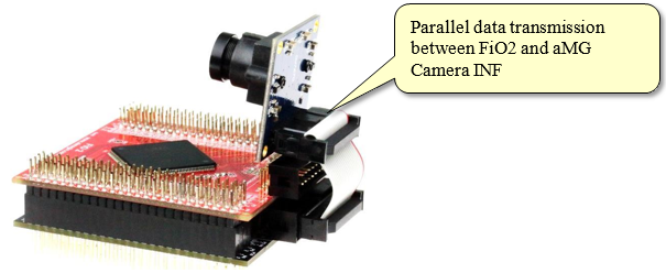
Figure 1‑1: Parallel data transmission between FiO2 and aMG Camera INF
Communication between microcontroller and external device can be classified into two types:
- Parallel Communication is between the transmitter and receiver when multiple binary bits are transmitted simultaneously. The advantage of parallel communication is high data transfer rate. For example, STM32F4DISCOVERY is connected with the LCD display which is connected with a camera. Furthermore STM32F4DISCOVERY is also connected with external RAM memory which is interfaced between two devices. It is not a good idea to use a single Bus for this purpose as application requires large number of external devices.
- Serial communication is a type of transmission when only a single bit is transmitted at a time. This type of communication is cheap and simple in terms of hardware complexity but slower than parallel communication.
In STM32F4DISCOVERY, there are many types of communication module UART, I2C, SPI, USB, CAN bus and Ethernet etc. In this section, UART module will be discussed.
1.1 Introduction to UART Communication Module
UART stands for Universal Asynchronous Receiver Transmitter that will connect and communicate with serial devices such as computers, RFID, GPS, GSM module, Wi-Fi module etc.
The advantages of using asynchronous communication is availability of full duplex communication i.e. it can send and receive data between the transmitter and receiver simultaneously and do not require clock synchronization for data transfer. The universal designation indicates that the data format and transmission speeds are configurable.

Figure 1‑2: Communication model for Universal Asynchronous Receiver Transmitter [1]
Figure 1‑2 shows the format of UART communication with users to define these properties Following are some typical configurations;
- Start bit status: Low;
- User can set the number of data bits to be 8 or 9;
- User can set the parity bit to even or odd or none;
- Stop bit with 0.5, 1, 1.5 or 2 bits.
In addition, users should consult the voltage level of the signal required by UART communication.
- TTL digital signal level is more commonly used. The logic state “0” is the voltage of 0 V and logic state “1” is the voltage of 3.3 or 5 V;
- RS232 level that is used by the computer logic “0” is -5 or -13 V and logic state “1” is voltage of +5 or +13V.
Figure 1‑3 shows the connection between the serial communication Transmit Data (Tx) pin of transmitter with Received Data (Rx) pins of the receiver to send and receive the data. Transmitter and receiver should have a common ground. If the devices are connected with different voltage levels then additional electronic components like MAX232 [2] should be added in path to adjust the voltage level.
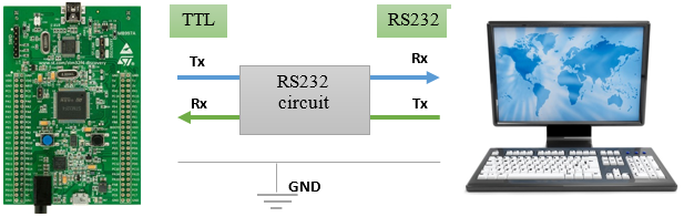
Figure 1‑3: UART connection
The blockset responsible for transfer of data via UART protocol in STM32F4DISCOVERY can be accessed from Simulink library >> Waijung Blockset >> STM32F4 Target >> On Peripheral Chip >> UART consisting of UART setup, UART Tx and UART Rx block
If users want to use UART STM32F4DISCOVERY, then users need to have UART Setup Block in Simulink model.
- Enable pin GPIO clock for Tx, Rx, RTS and CTS;
- Set the pin STM32F4 for Tx, Rx, RTS and CTS;
- Select the UART Module Clock;
- Set up the UART;
- Enable DMA clock;
- Setting the Direct Memory Access for accessing information.
The UART Setup Block features are shown in Figure 1‑4. In the settings, serial communication port UART module 3 is used and PD8 and PD9 are used for Tx and Rx respectively. Baud rate is set to be 115200 with no parity bit, 1 stop bit.
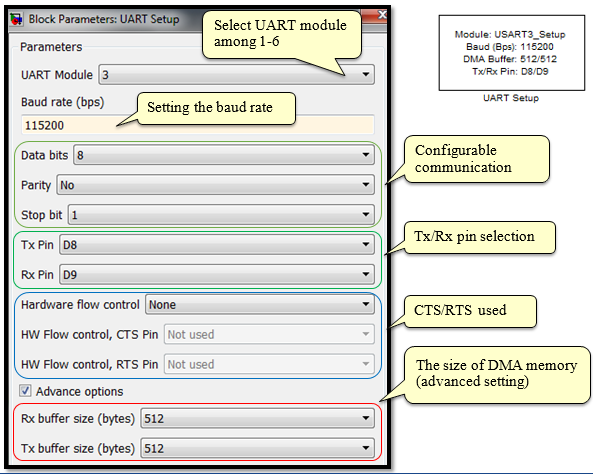
Figure 1‑4: UART setup configuration
2 Experiment using UART Communication Port
2.1 Equipment used in this Experiment
In this section, introduction to aMG USB Converter-N-Adapter is given which has FT2232H high speed USB 2.0 (480 Mbps), a UART/FIFO two channels [3]. Such type of hardware is ideal to be used for Hardware In Loop (HIL) simulation.
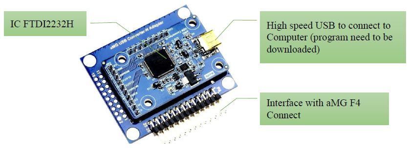
Figure 2‑1: Characteristics of aMG USB Converter-N-Adapter [3]
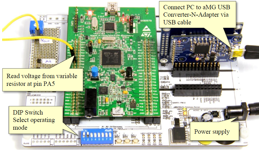
Figure 2‑2: STM32F4DISCOVERY and PC connection
When aMG F4 Connect is connected with the power supply and aMG USB Converter-N Adapter with the PC for the first time, the user must make sure to follow the below mentioned procedure.
Go to Start Menu, right click on Computer icon and selection the properties. A new window will appear as shown in Figure 2‑3.
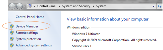
Figure 2‑3: Pop up window
Go to device manager, expand the Ports (Com & LPT) which is managing the computer’s parallel ports and serial communication which is shown in Figure 2‑4.

Figure 2‑4: Device manager window to confirm port number
In addition to the above check of port number, the user need to set the Com Port Latency Time to higher speed which will help in improvement of data transmission speed which is essential in Hard in Loop Latency Timer setting. This can be done by following way.
- Select the first USB with which aMG USB Converter-N Adapter is connected. Go the Properties and then Port settings of the Com Port as shown in Figure 2‑5 and click on Advanced.
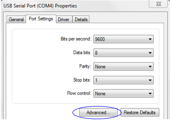
Figure 2‑5: Advanced settings for Com Port connected with aMG USB Converter-N Adapter
- Set the Latency time to 1ms (the default time is 16 ms). This is shown in Figure 2‑6
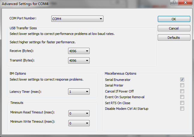
Figure 2‑6: Changing the Latency Timer for Com Port
After reviewing the Com Port number and Latency Timer, next is to set the Com Port on the Host Serial Blockset (when using Hard In the Loop Simulation) or serial communications ports. In the next section, we will introduce Freeware programs to communicate through the serial port.
2.2 Using Serial Communication port
Tera Term is a freeware program which can be used for serial communication. The program can be downloaded from http://www.ayera.com/teraterm/. This program works only with Microsoft Windows operating system. Users can configure the communication ports and the procedure is as follows:
- After downloading the program, click on ttempro.exe Tera Term. A popup window will appear as shown in Figure 2‑7.
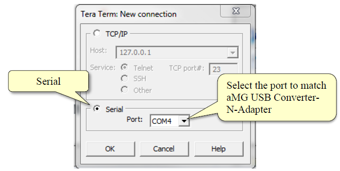
Figure 2‑7: Selecting communication port in Tera Term
- In the terminal window, user need to go to Setup -> Terminal to do configuration which is shown in Figure 2‑8.
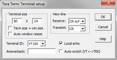
Figure 2‑8: Setting terminal window in Tera Term program
- In the terminal window, go to Setup -> Serial port to set the properties of the selected communication port. The configuration is shown in Figure 2‑9, in which baud rate is set to be 115200 bps, Data bits are 8, no parity bit and one stop bit.
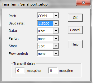
Figure 2‑9: Serial port settings
PuTTY is a client program for the SSH, Telnet and Rlogin network protocols. Commands from the clients can be sent to the server through internet via serial communication port. PuTTY can work on Windows and Linux platforms and can be downloaded from http://www.chiark.greenend.org.uk/~sgtatham/putty/download.html
Following steps are helpful in while using the serial port with putty
- After downloading the putty program, run Putty.exe. A pop-up window will appear as shown in Figure 2‑10.
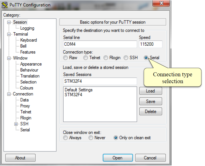
Figure 2‑10: Putty configuration
- Set the terminal as shown in Figure 2‑11

Figure 2‑11: Terminal settings in Putty
Serial port settings for Putty are shown in Figure 2‑12. The baud rate is set to be 115200 bps with no parity bit and one stop bit.
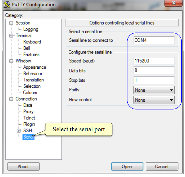
Figure 2‑12: Serial port settings for Putty
2.3 How to use UART Tx Block
UART Tx Block is used to send data out of the microcontroller to the external devices via Tx pins and provides a convenient way for the transfer of data. There are three Packet Modes available and user can choose any one of them. These modes are ASCII Mode, Binary Mode and String Buffer Mode.
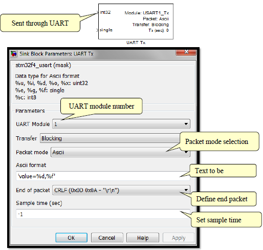
Figure 2‑13: UART Tx Block settings
2.4 Experimental Demonstration of Message Transmission from STM32F4DISCOVERY to Computer
Purpose
- To enable the user to understand the operation mode of UART Tx Block Packet mode;
- To enable the user to understand the Binary code and ASCII data.

Figure 2‑14: Simulink model for UART Tx
When the program is downloaded in STM32F4DISCOVERY, the text included in ASCII Format Dialog and End of Packet i.e. ‘Greeting from Waijung \n \r \ n’ will appear in Tera Term window and the same message will repeat after every 1 second (sampling time). This is shown in Figure 2‑15.
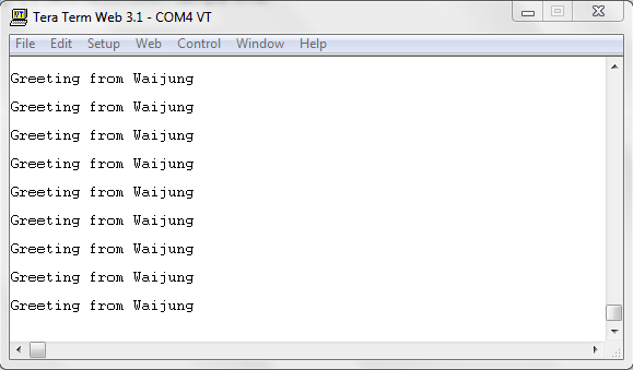
Figure 2‑15: Tera Term display message received via UART communication port
Question : What should be done if user want to set UART Tx Block messages immediately after newline?
Answer : “\n” is the newline. The example shown above ASCII Format is ‘Greeting from Waijung\n’ and End of Packet is CRLF (0x0D 0x0A – “\r\n”).
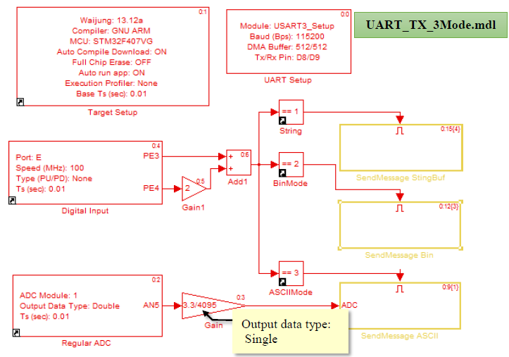
Figure 2‑16: Simulink model for sending messages in Packet mode
Simulink Model in Figure 2‑16 is an example of the Enable Subsystem for sending messages using Packet Mode or to read the digital signal. Dip-Switch is an optional mode of operation and is functionality is as follows.
- When DIP-SW1 is set to ON and DIP-SW2 to OFF signal from the switch activates Sub System “SendMessage Stringbuf” Block which is an example of using the UART TX Packet Mode. Figure 2‑17 contains a String Buffer;
- Volatile Data Storage Block, a String variable named s;
- String Buffer Processing Block is configured to use a String variable or text;
- UART Tx Block by Packet Mode and String Buffer.
When the program is running, the terminal window will display “Greeting from Waijung” every 5 seconds.
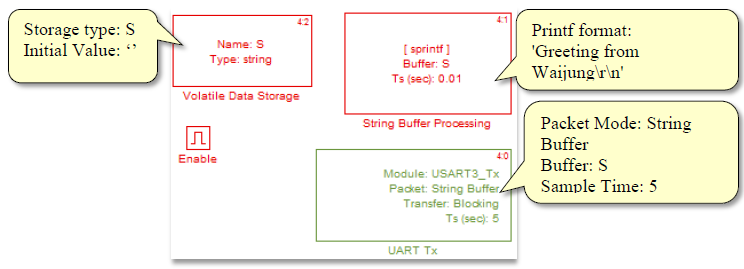
Figure 2-17: Subsystem Block for sending messages using the Packet Mode and String Buffer
When DIP-SW1 is set to OFF and DIP-SW2 is ON signal from the switch activates Sub System “SendMessage Bin”, which is an example of using the UART TX Binary Packet Mode. Figure 2‑18 contains the Sub System.
- Counter Limited Block to send the numbers from 0 to 106 and counts every 1 second;
- Constant Block, which has the hexadecimal value 0x20;
- UART Tx Block using Binary Packet Mode.
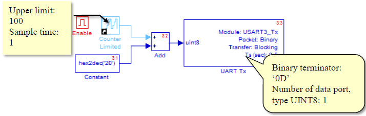
Figure 2-18: Subsystem Block for sending messages using the Binary Packet Mode
The Terminal window displays a character-only (ASCII Printable Character) from The ASCII Code Table [3]. In Figure 2‑19 hexadecimal code 0x00 to 0x1F which are used as an example. ASCII Control Character 0x0A is for the new line. ASCII Printable Character starts from 0x20.
When the program is running in the TeraTerm window, characters will be displayed after every 1 second as shown in the table without newline (because there is no “\ n” or 0x0A) but begins to the left every time.
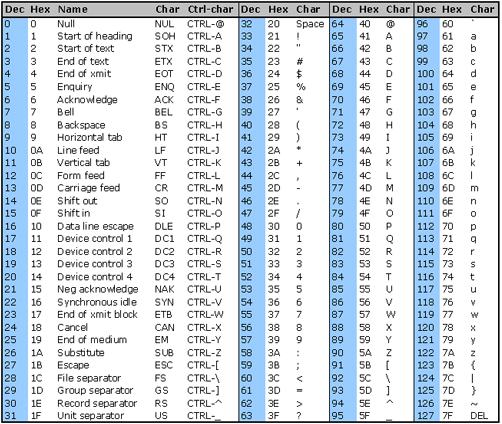
Figure 2-19: ASCII table [3]
- When DIP-SW1 and DIP-SW2 are ON signal from the switch activates Sub System “SendMessage Ascii” which exemplifies the use UART TX ASCII Packet Mode. In Figure 2‑20, Terminal window displays the message “Value = and the reading of the variable resistor.
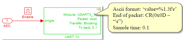
Figure 2-20: Subsystem Block for sending messages using the ASCII Packet Mode
Figure 2‑21 shows the Enable Sub System Block. Users can configure the UART Tx Block Packet Mode and sampling time.
Figure 2-21: Terminal displays messages received via the UART communication mode
2.5 How to Use UART Rx Block
UART Rx Block is used to receive data from external devices through the Rx pins. ASCII mode is selected for the Packet mode however user can choose from the three modes available.
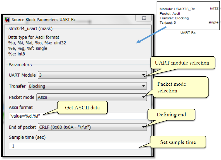
Figure 2-22: Settings while using UART RX Block in ASCII Mode
2.6 Experiments using Computers
Purpose
- To enable the users to use UART Rx Block for receiving data from computer.
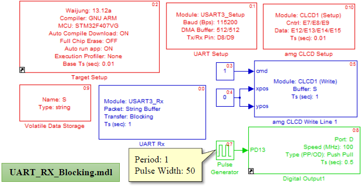
Figure 2-23: Simulink model for data transmission between UART Rx Blocking and computer
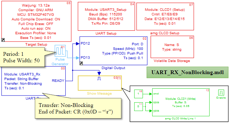
Figure 2-24: Simulink model for data transmission between UART Rx Non-Blocking and computer
Figure 2‑23 and Figure 2‑24 show Simulink model for the experiment for the transfer of data from computer in Blocking and Non-blocking mode respectively. The Simulink model need to be downloaded into STM32F4DISCOVERY. User can open Tera Term window and type the text “Hello Waijung” on the Terminal window. This message will appear on the LED attached with STM32F4DISCOVERY via USB when Enter key is pressed. This is shown in Figure 2‑25.
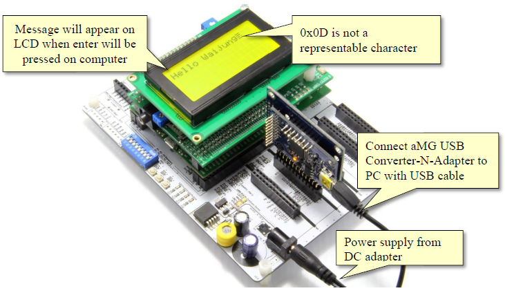
Figure 2 25: Receiving messages from the computer
When user presses Enter to specify that the message is finished, 0x0d will appear on the display but it will not appear on the LCD display of the microcontroller.
In this example, users can observe the different behavior of UART_RX Block with Blocking and Non-Blocking. UART_RX block with blocking wait for completion of the running command before running another therefore LED2 is not flashing.
For the model in Figure 2‑24, when the user selects a UART_Rx Block with Non-Blocking, the ready signal will indicate that the message has been complete. It means that the model can accept other commands while the text is still not complete without blocking the incoming messages (note that LED2 light is flashing).
2.7 Peripheral Controller via Serial Communication
Purpose
- Enable the users to understand the performance of UART Rx Block using Packet mode and ACSII Format;
- Enable the users to control Peripheral Serial Communication.
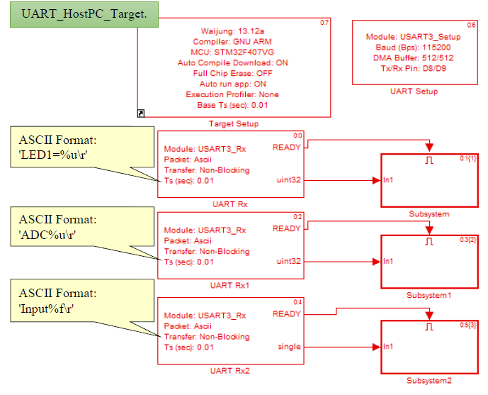
Figure 2-26: Simulink model for Peripheral control via Serial Communication
Notice that users can use the same UART Rx Module with multiple blocks but within the same Packet Mode
Download Simulink model on STM32F4DISCOVERy and connect with Tera Term. Users can type the following command.
When send command LED1=1, press Enter UART Rx Block check the received message is “LED1=%u\r” which Activate Subsystem Block then the value %u will be sent to Subsystem Block as shown in Figure 2‑27. Inside of the system containing Digital Output Block to control ON/OFF for LED1 that is connected to PD12 pin. LED will be ON if the read value is not equal to zero, so set LED1=0 then Enter, the LED1 will off and UART Tx Block send response “>>OK” to user.
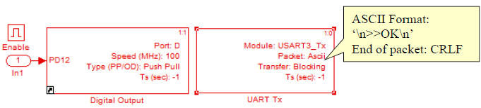
Figure 2-27: Subsystem block for light controlled LED
When printing ADC% u? Press Enter UART Rx1 Block, check the messages received is “ADC% u \ r” to Activate Subsystem1 Block then it will display the voltage reading.

Figure 2-28: Subsystem block for displaying voltage reading at pin PA5
When command Input is given followed by a number and then Enter , UART Rx2 Block verify received message “Input%f\r” to Activate Subsystem2 Block and then the read value (%f) will be sent to Subsystem Block as in Figure 2‑29 then prompt the text Your Input is: and the input number.
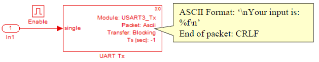
Figure 2 29: Subsystem block for displaying input number
Figure 2‑30 the message shown on terminal screen of program TerTerm is “>>OK” after ON-OFF the LED. Show value of voltage that read from PA5 and the received number in floating type.
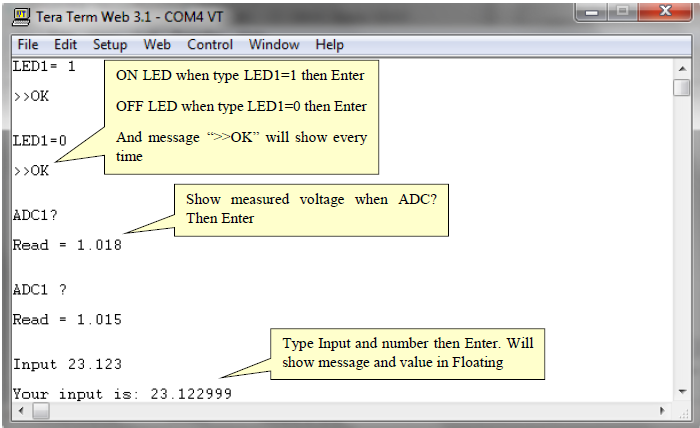
Figure 2‑30: Result of peripheral control by computer
3 Experiment to Demonstrate Communication between Microcontrollers
Serial communication between the microcontrollers can happen directly. Therefore, users must make sure that the voltage levels between sender and receiver (in this case both are microcontrollers) are the same. This example use 2 set of microcontroller board. The first board is STM32F4DISCOVERY and the second board is FiO2 that uses microcontroller model STM32F417IG installed on board aMG F4 Connect. Both boards have voltage in serial cable approximately 3.3V.
3.1 Experiment for communication between Microcontrollers in Blocking type.
Objective:
To make users understand serial communication between microcontroller
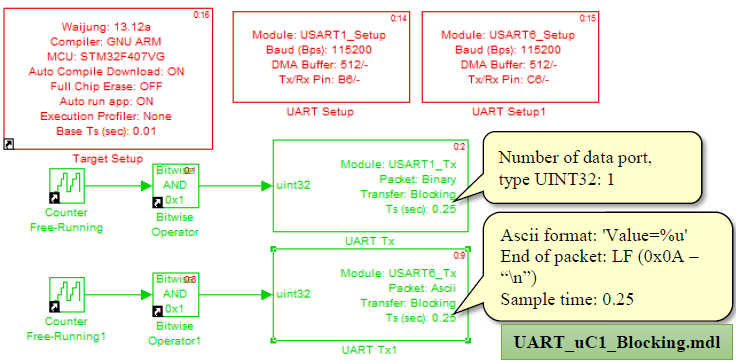
Figure 3‑1: Simulink model for message blocking for board 1
After downloading the Simulink model into STM32F4DISCOVERY, the numbers 0 and 1 will be sent alternatively in Packet Binary by UART Module 1 via PB6 pin. And message ‘Value=%u\n’ will be sent by UART Module 6 via PC6 pin every 0.25 seconds.
Second board will be receiver. User must download model in Figure 3‑2 into FiO2 that have two blocks of UART RX Block. The first block will receive binary data and the second block will receive Ascii data. Blocks will receive data every 0.01 second. In order to make received data correct, the receiver should have double frequency rate to transmitter.
The received data from UART will use to control ON/OFF LED1 and LED2 on aMG F4 Connect. Both LEDs will blink every 0.25 second.
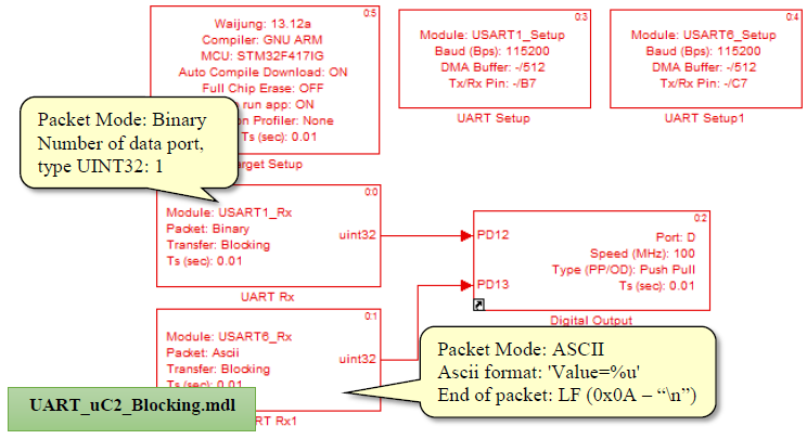
Figure 3‑2: Simulink model for text blocking on board 2
User can freely choose UART module for send and receive data by selecting module in UART Setup Block then connect Tx-Rx that matched to selected module. Figure 3‑3 shows the serial cable connections between microcontrollers. Both boards use UART Module 1 and 6.
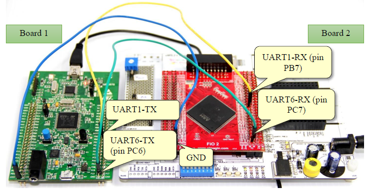
Figure 3‑3: Communication between the microcontrollers (blocking)
3.2 Experiment for Communication between Microcontroller in Non-Blocking type.
Objective:
- To make users understand serial communication between the microcontrollers in Non-Blocking type.
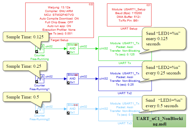
Figure 3‑4: Simulink Model for send data in Non-Blocking type in Board 1
Simulink model shown in Figure 3‑4 have 3 blocks of Non-Blocking UART TX. Each block will send different Ascii data and different frequency. After downloading model into STM32F4DISCOVERY, the first board will send “LED1=%u\n” every 0.125 second. UART Tx2 Block will send “LED2=%u\n” every 0.25 second and UART TX3 Block will send “LED3=%u\n” every 0.5 second via only PB6 pin.
Second board will be a receiver. User must download model in Figure 3‑5 into FiO2 that have 3 blocks of Non-Blocking UART RX Block. Each block will read Ascii data in every 0.001 second. When received the messages value, that value will be used to control ON/OFF LED within Enable Subsystem Block. In order to make the received data correct, the receiver should have double frequency rate to transmitter, same as in Blocking type.
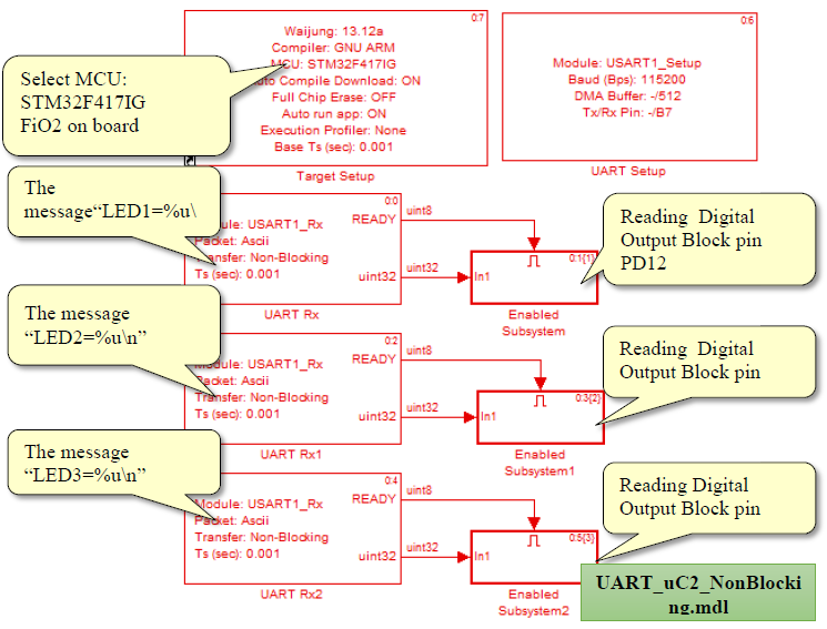
Figure 3‑5: Simulink Model for receive data in Non-Blocking type in Board 2
Figure 3‑6 shows serial connection between microcontroller using UART module 1 for board 1 and board 2.
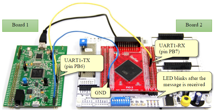
Figure 3‑6: Communication between microcontrollers (non-blocking)
4 References
- STMicroelectronics, RM0090: STM32F40xxx Reference Manual [Online], 2013
- Texas Instruments, MAX232-Dual EIA-232 driver/receivers [Online]. Available: http://www.ti.com/lit/ds/symlink/max232.pdf. [2004]
- Future Technology Device International, FT2232H DUAL HIGH SPEED USB TO MULTIPURPOSE UART/FIFO IC [Online]. Avaible: http://www.ftdichip.com/Support/Documents/DataSheets/ICs/DS_FT2232H.pdf. [2012].
- Aimagin, aMG USB Converter – N2 [Online]. Available: https://www.aimagin.com/amg-usb-converter-n2.html. [Accessed 18 February 2014].
- CommFront, ASCII Table / ASCII Chart – Standard and Extended ASCII Codes [Online]. Available: http://www.commfront.com/ascii-chart-table.htm [Accessed 9 January 2014]
- Jimbo, RS-232 vs. TTL Serial Communication- SparkFun Electronics, Sparkfun Electronics:, 23 November 2010. [Online]. Available: https://www.sparkfun.com/tutorials/215
- Ayera Technologies , TeraTerm 3.1.3 – Telnet, SSH2, SSL Client with built in Web Server 2002. [Online]. Available: http://www.ayera.com/teraterm/
- Tatham, PuTTY: A Free Telnet/SSH Client, [Online]. Available: http://www.chiark.greenend.org.uk/~sgtatham/putty/