Introduction to Waijung and Matlab & Simulink
This article introduces you to Waijung and Matlab & Simulink for uses in embedded system development, that can be much faster, easier, and more fun.
1 Background
Computer and handheld devices (like smart phones, tablets) have revolutionized the world. Now we can play online games with our friends, share media, manage inventory, analyzing huge stock exchange data and many more things with these devices while sitting at a remote location. Having a video call on social media websites or doing online shopping is now quite easy but how these things are made possible.
Computer is a dump machine in-fact a very dump machine. Computers by itself cannot do anything. It don’t have power to make decisions. They are programmed so that they can act according to our ‘clicks’ and ‘touches’. To program a tablet or a computer to follow the instructions is not that straight forward. A house which looks very clean and beautiful is the result of hard efforts of the cleaner, home décor designer and the architect. An application ‘app’ available on our smart tablets – programmers and developers who work round the clock to deliver it.
1.1 What is a Computer?
A computer is an electronics device which works under the set of instructions stored in its own memory. From this definition we can analyses previously it was mentioned that computer is a dump device and it cannot do anything/make decisions at its own. Whatever is stored inside its own memory, it will work according to that. We can visualize the information process cycle of the computer or related device as in Figure 1.

Figure 1: Information Process Cycle
It is interesting to share information that a computer not only contains electric and electronic components but also some mechanical components [1]. These components are known as hardware. We can categorize the computer hardware as in Figure 2.

Figure 2: Computer hardware
1.1.1 What is an Operating System?
An operating system (OS) is a set of programs containing instructions that work in conjunction with the hardware to perform the desired tasks. Main responsibilities of an OS are:
- Start and shutdown computer
- Provide user interface
- Manage programs
- Memory management
- Coordinate tasks
- Configuration of devices
- Establish internet connection
- Monitor performance
- Provide utilities
- Network control
- Administer security
1.1.2 Classification of Computers
We can broadly classify the computers as:
- Mobile computers and mobile devices
- Personal computers
- Game consoles
- Servers
- Mainframes
- Supercomputers
- Embedded computers
1.2 What is a Microcontroller?
A micro-controller is an integrated circuit with built-in Central Processing Unit (CPU), programming and non-programmable memory, input/output (I/O) ports, digital to analog convertor and vice versa.
Now a question can come in mind that what is the difference between a microcontroller and microprocessor of general purpose computer. Table 1 will explain this question.
Table 1: Comparison between Microprocessor and Microcontroller

1.3 What is an Embedded System?
An embedded system is a computer system with a dedicated function within a larger mechanical or electrical system, often with real-time computing constraints2. From the definition, it can be observed that an embedded system is different from general purpose computer but may contain similar components.
1.3.1 Why Embedded Systems?
An embedded system can be called as a mini computer which has en ability to work in an intelligent standalone manner. Embedded systems are widely in used because they are:
- Cheap
- Energy efficient
- Compact size
- Moderate weight
1.3.2 Examples of Embedded System
Examples of embedded system are as follows:
- Microwave ovens
- Cell phones
- Calculators
- Digital watches
- GPS devices
- Heart monitors
- Laser printers
- Engine controllers
- Digital cameras
- MP3 player
- Washing machines
- Set-up box
- Television
- Remote controls
- Bread machines
- Elevators
- Coffee makers
- Thermostats
- Parking meters
- Fax machines
- Cash registers
- Treadmills
- Gas pumps,
- Card readers
2 What is MATLAB?
MALTAB is developed by MathWorks which is a leading developer of mathematical computation software. MATLAB® is a high-level language and interactive environment for numerical computation, visualization, and programming [3]. The definition above have two keywords. When we refer to ‘high-level language’ the first thing which comes to mind should be: it is easy to do programming, have a lot of built-in functions and developing a program is simpler and more understandable to human beings. ‘Interactive environment for MATLAB refers to the availability of ‘Apps’, Graphical User Interface (GUI), multi-dimensional visualization.
MATLAB is used by mathematicians and statisticians as it helps them in solving linear and differential equations, applying optimization techniques to solve their problems, availability of statistical and machine learning algorithms for organizing, analyzing and modeling the data etc. MATLAB is used by engineers and scientists as it helps them in modeling an engineering system like vehicular area network, communication system, and aeronautical system. It helps them in signal and image processing, data visualization, control and fuzzy logic systems and many more. MATLAB is used by economists and financiers as functions in MATLAB are available for modeling an economic and financial data. Applications of MATLAB are not exhausted here. MATLAB can be used by any person who wants a computerized solution for his/her problem. As the programming in MATLAB is far easier, people often use MATLAB to write their program in MATLAB and then convert them into C or C++ in which writing code is quite hard as compared to MATLAB. More than 1 million people from industry and academia are using MATLAB – the language of technical computing. By now, reader can feel that MATLAB can be really helpful in solving a simple as well as complex problems.
2.1 Some Examples
Before some very basic examples are introduced in this section, it is assumed that the user has already installed MATLAB correctly and have some fundamental knowledge about programming. While installation, a user might have observed one thing i.e. installation time of MATLAB is significant. This is because of the richness of MATLAB in terms of libraries, built-in functions, variety of toolboxes, coders, blocksets etc. To start with, a MATLAB code to generate a sine wave is given and how we can visualize that sine wave.
2.1.1 Example 1: Generating a Sine Wave using MATLAB
This example shows how sine wave and cosine wave can be generated. Furthermore they are plotted against time to observe their phase difference. In order to do so, we need to know the two important things.
- What should be the center frequency of the signal?
- What should be the sampling frequency of the signal? If the sampling frequency is too low then we will not be able to get a nice sinusoidal wave. If the sampling frequency is too high then wave will be very smooth but computation time will be increased.
MATLAB Code

Figure 3: Plotting a sine and cosine wave
2.1.2 Example 2: Discrete Fourier Transform and Power Spectral Density Calculations
Moving a step forward, we know that a simple communication system consists of three entities i.e. transmitter, channel and the receiver. Channel can be wired (copper cable, twisted pair, optical fiber) or wireless (air, vacuum) [4]. Channel is the point where most of the noise is introduced in the transmitted signal. In the code below we do the following steps:
- Create two sine waves of different frequencies
- Add some random noise to the sine waves
- Do plotting to observe the effect of noise on the signal. If the noise is very strong then the signal will be distorted considerably and if the noise if low then the effect will not be strong.
- Using Fast Fourier Transform (FFT) algorithm to compute the Discrete Fourier Transform (DTF).
- Computing power spectral density
- Plot and observe the graphs
We can observe that even after the addition of the noise, FFT enables us to recover back the center frequency of the two signals. At the bottom of Figure 4, we can observe two peaks at 50Hz and 120Hz respectively which are the same as the signal frequency which we choose in the beginning.
MATLAB CODE
% Show the use of the FFT function for spectral analysis.
% Create signal at 50 Hz and 120 Hz
t = 0:.001:.25;
x1 = sin(2*pi*50*t);
x2 = sin(2*pi*120*t);
x = x1 + x2;
% Add some random noise
y = x + 2*randn(size(t));
subplot(611),plot(x1), title(‘Sine wave at 50 Hz’)
subplot(612),plot(x2), title(‘Sine wave at 120 Hz’)
subplot(613),plot(x), title(‘Sine wave at 50 Hz + 120 Hz’)
subplot(614),plot(y), title(‘Noisy time domain signal’)
% Finding the discrete Fourier transform
Y = fft(y,256);
% Compute the power spectral density
Pyy = Y.*conj(Y)/256;
f = 1000/256*(0:127);
subplot(615),plot(y), title(‘Noisy time domain signal’)
subplot(616), plot(f,Pyy(1:128)), title(‘Power spectral density’)
xlabel(‘Frequency (Hz)’)
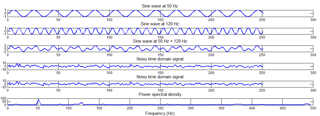
Figure 4: Discrete Fourier transform and power spectral density calculations
2.1.3 Example 3: Representing Data in Plots
No matter from which domain a researcher is, it is always important for him/her to represent his/her work in a meaningful way. Graphs are one excellent way of representing a large data which can yield a meaningful information. Fortunately, MATLAB is very rich in plotting graphs and have a lot of built-in functions. In the code below, a reader can find ways how a data can be represented using MATLAB. In this example, same data is represented in seven different ways i.e. scatter, stem, polar, error-bar, stair-step, bar and line plot.
MATLAB CODE
clear all, close all
% Scatter Plot
figure; load count.dat
scatter(count(:,1),count(:,2),’r*’)
xlabel(‘Number of Cars on Street A’);
ylabel(‘Number of Cars on Street B’);
title(‘Scatter Plot’)
% Stem Plot
figure; x = 0:0.1:4;
y = sin(x.^2).*exp(-x);
stem(x,y)
title(‘Stem Plot’)
% Polar Plot
figure; t=0:0.01:2*pi;
polar(t,abs(sin(2*t).*cos(2*t)));
title(‘Polar Plot’)
% Errorbar Plot
figure; x=-2:0.1:2;
y=erf(x); e = rand(size(x))/10;
errorbar(x,y,e);
title(‘Errorbar Plot’)
% Stairstep Plot
figure; x=0:0.25:10;
stairs(x,sin(x));
title(‘Stairstep Plot’)
% Bar Plot
figure; x = -2.9:0.2:2.9;
bar(x,exp(-x.*x));
title(‘Bar Plot’)
% Line Plot
figure; x=0:0.05:5;
y=sin(x.^2);
plot(x,y);
xlabel(‘Time’); ylabel(‘Amplitude’)
title(‘Line Plot’)

Figure 5: Different ways of representing data
2.1.4 Example 4: Drawing a Heart
Matlab is not only meant for doing some serious research but something romantic can also be created using few lines of MATLAB. Here is a sample code to create a heart.
MATLAB CODE
close all; clear all; clc
v = -1.5:.02:1.5;
[x,y,z] = meshgrid(v,v,v);
w = (2*x.^2+y.^2+z.^2-1).^3-(1/10)*x.^2.*z.^3-y.^2.*z.^3;
hp = patch(isosurface(w,0));
set(hp,’facecolor’,’r’,’edgecolor’,’none’)
light; lighting phong;
view(99,18)

Figure 6: Drawing a Heart
For more examples, please refer to Section ‘List of Resources’.
2.2 MATLAB TOOLBOXES
By today, MATLAB has more than 40 toolboxes which allows scientist and researchers to complete their tasks with easy. The list of the toolbox can be found from the following link.
http://www.mathworks.com/products/
2.2.1 To check which toolboxes are installed in your MATLAB.
In order to check which toolboxes, blocksets and version of MATLAB is installed in the computer, user need to type command ‘ver’ in command line.
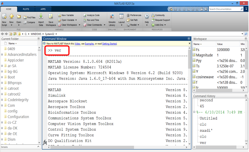
Figure 7: Using command ver to check MATLAB version and installation products
3 What is Simulink?
Simulink is a block diagram environment for multi-domain simulation and Model-Based Design. It supports simulation, automatic code generation, and continuous test and verification of embedded systems [5]. Like MATLAB, Simulink was also developed by Mathworks. Its principal interface is a graphical block tool and a customizable set of block libraries. Simulink can be used in conjunction with the MATLAB. Capabilities of Simulink are as follows:

Figure 8: Simulink capabilities
Aimagin is specialized in utilizing the capability of Simulink to connect with hardware. The later part of this tutorial will leads us to connect Aimagin hardware with Simulink but before tutorial goes into that detail it is very important to understand the Simulink first.
3.1 Start using Simulink
In order to run Simulink, user need to type simulink in the MATLAB command window. MathWorks also provides an icon to Simulink but the icon position and colors may vary with the different versions of MATLAB so for the beginning it is preferred to go by typing Simulink in MATLAB command window which works on all the version of MATLAB. The result is shown in Figure 9.
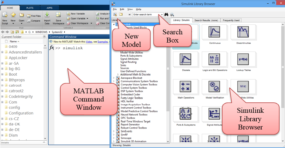
Figure 9: Starting Simulink
A list of block library will appear. User can select a block of desired characteristics from these libraries. The most commonly use block libraries are:
- Integrator
- State Space
- Transfer Function
- Transport Delay
- Add
- Gain
- Product
- Sum
- Mux
- Demux
- Scope
- XY Graph
- Step
- Signal Generator
- Ramp
- Random Number
- AWGN Channel
To create a new model, the user need to do go to File -> New ->Model. In order to open an existing model, user need to go to _ File ->Open ->_ Specify the model location on the hard disk.

Figure 10: Opening a new model
When we click on Model, a new window will open which is shown below in Figure 11.
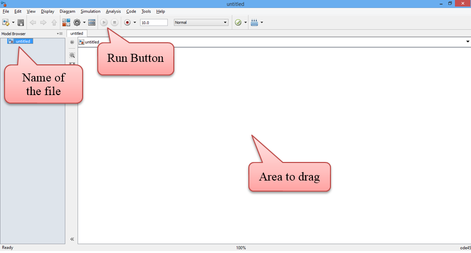
Figure 11: New model in Simulink
Now, we are all set to create a model. We need to first plan, what actually we want to build and what are the components required. Please keep in mind that just by simply connecting the blocks in the model, things will not work. Input of the second block must be matching with the output of the first block and so on. Indeed drawing modeling in Simulink is far easier than doing programming but don’t think Simulink like Microsoft Visio. Don’t get disappointed if while running the model, you get some error. Read about the block properties, the background knowledge of relevant field and the nature of input/output signals. As like other learning tools, beginning is little difficult but things becomes easier with the passage of time. So we start with a simple case and our agenda is to create a detailed digital communication system.
3.2 Examples using Simulink
3.2.1 Example1: Creating and Observing a Sine-wave
We start with the simplest case. Open a new model. Save a model with a legit name. Now a reader should think before going further, what blocks are required in order to create and sine wave and see the created sine wave. The answer is very simple. Two things i.e. something which can generate a sine wave and something which is like a oscilloscope in the labs to see it. We search for these two items in ‘Simulink Library Browser’. When right choice of component is found, simply drag that block to the new model created.

Figure 12: Dragging appropriate components to the model
Now both the required blocks are with us. Now it’s the time to see if it is possible that by doing so simple task, sine wave can be created and observed. Click on ‘play’ button or Ctrl + T. Simulink will start compiling and when it’s done, double click on scope button the observe the output which is shown in Figure 13. Please note that the properties of Sine wave block (or any other block) can be customized by double click on the block. Similarly, model configuration parameters can be changed from Simulation -> Model Configuration Parameters.

Figure 13: Observing the sine wave
Please note that in order to obtain the results in Figure 13, following customization has been done.
- Amplitude of the sine wave has been changed to 5 by ‘double click’ on Sine Wave.
- By going to Simulation -> Model Configuration Parameters, two changes have been made. Simulation stop time to 20.0 and Max step size to 0.2 from auto.
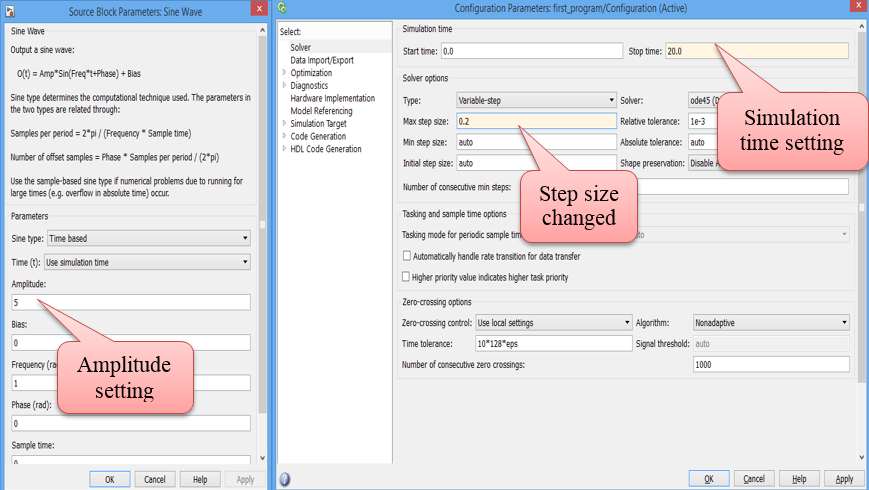
Figure 14: Setting model configuration parameters
- When graph is obtained after running the model and double click on the scope. Click on setting icon and changed the style of line. Note any color of thickness to the sine wave graph can be assigned. The remaining properties are left on reader to explore.

Figure 15: Scope parameter properties configuration
3.2.2 Example 2: Integrating a sine wave
Now, we can move forward quickly. For the next example, we require the following blocks.
- Sine wave
- Integrator
- Scope
- Gain
- Bus creator
These blocks are arranged in the following order as shown in Figure 16 and the output is shown in Figure 17.

Figure 16: Integrating a sine wave

Figure 17: Output of the block diagram of Figure 16
Yellow line is for the output after passing through gain and integrator and purple line is for the sine wave generated. It can be observed that it is a simple procedure to apply gain and applying little complex mathematical operation like integration.
3.2.3 Example 3: Inverted Pendulum on a cart
Figure 18 shows the inverted pendulum on the cart. This is a typical engineering problems since ages and it can be modeled and visualized in Simulink with so ease.

Figure 18: Inverted pendulum on the cart
For more examples, please refer to Section ‘List of Resources’.
4 In which programming language MATLAB is written?
After analyzing some program written in MALTAB, a question may come in reader’s mind that in which programming language MATLAB is written? The answer to this question is not that straightforward. MATLAB is not written in a single programming language but in many programming languages which are:
- C
- C++
- Common Intermediate Language (CIL)
- NVidia CUA
- Bash Shell Script
- Fortran
- Java
- MATLAB
- Perl Windows Batch Files
5 Pros and Cons of Using MATLAB/Simulink
5.1 Pros
MATLAB/Simulink have a lot of advantages which engineers, researchers, scientists and students can enjoy [6].
- Easy to use and simple for designing and analyzing engineering and non-engineering systems.
- Basic data element is matrix and MATLAB has mathematical operations that works on matrix are built in.
- The graphical output of optimized for interaction.
- More than 1 million users are using MATLAB. A very lucid online documentation support is available both from MathWorks as well as other websites.
- MathWorks is also very active in providing online support.
5.2 Cons
It uses a large amount of memory and slow down the computer.
- It sits ‘on top’ of operating system thus can only be allocated CPU time which operating system allows. This is a bottle neck for using MATLAB for high speed real time applications.
6 What is the Problem?
From the discussion above, reader can realize that the programming in C/C++/Assembly is not very easy however MATLAB/Simulink is a powerful tool to overcome this issue. Specifically talking about Simulink, things can be done by connecting the respective blocks without writing even a single line of code. While designing and analyzing a system like intelligent control system/signal processing/communication system etc. MATLAB/Simulink gives wings i.e. design and analysis process is simple and easy but comprehensive. Simulation using MATLAB/Simulink tools will save time and cost. Furthermore, detailed analysis gives an opportunity to avoid any unwanted situation.
6.1 Real System Implementation
For the real system implementation using MATLAB/Simulink tool, there are two major concerns.
- Connecting hardware with MATLAB/Simulink
- Time sensitive applications bottle neck
In order to connect hardware with Simulink, Aimagin has made a customized blockset named ‘Waijung’. This provide an opportunity the Aimagin hardware with the Simulink and a user can realize a real system. So with Waijung blockset, from design to implementation, the whole process is fast, easy, fun and not forget to mention …NO C/C++ code is required. We explain the advantage of our blockset with an example. For example a user wants to make a chair. In order to make a chair he/she needs a hammer, nails, sandpaper and wood. Now there are two options available.
Option 1: Make hammer, nails and sandpaper yourself. Go to the forest to cut tree and bring wood. When everything is done, start making chair
Option 2: Buy/use already available hammer, nails, sandpaper and wood in the market and make a chair
Indeed option 2 is better than option 1 in terms of time and skills required.
MATLAB gives a tool to convert a MATLAB written code in C (and other languages) which can fit well in time sensitive applications. Generated code from Matlab contains more overhead than hand coding but the former one is faster a suitable for rapid prototyping. A detailed explanation how a C code can be generated from MATLAB algorithm is given in the following link.
http://blogs.mathworks.com/loren/2011/11/14/generating-c-code-from-your-matlab-algorithms/
6.2 Advise to use Waijung Blockset
Readers should not get an impression that merely connecting Aimagin hardware via USB with a computer will get everything done. For example if a user want to add two numbers using a calculator, then he must know that he should enter first number then press + button and then enter the second number. At the end, the user should press = button the get the output. Similarly using Waijung with hardware, the user must know the mathematics/equations involved while realizing a system, how to use the tools, how to connect the circuit, how circuit works etc.
7 List of Resources
7.1 Resources on Aimagin
Currently significant literature is available online and the company is constantly adding more and more literature, examples, tutorials and videos so that the users can benefit more from Aimagin products. To get hands on and for some mini projects, the users can refer to blog.aimagin.com where they can find more than 20 sample projects and tutorials.
Quick reference for sample project is as under
http://aimagin.com/blog/topics/sample-project-th/?lang=th
Quick reference for mini projects
http://aimagin.com/blog/mini-project-kmutnb-mechatronics-56/?lang=th
Quick reference for tutorials
http://aimagin.com/blog/topics/tutorials-th/?lang=th
Reference Manual about Waijung can be accessed from the below mentioned link. From here Waijung blockset can be downloaded.
Video tutorials which gives a great insight about our product can be accessed from
Information about Aimagin previous RapidSTM32 block set can be found from
A large resources in terms of tutorials, examples, videos books etc. are available. For instance
7.2 MATLAB Resources on the Web
Here is the list of few tutorials on the MATLAB. Please note that this is not a complete list but only very few references how to get started with MATLAB. After gaining the basic knowledge, the user can search for more resources of the web.
http://www.mathworks.com/academia/student_center/tutorials/launchpad.html
http://www.mathworks.com/academia/student_center/tutorials/?s_tid=gn_ac_sv_tu
http://www.math.utah.edu/lab/ms/matlab/matlab.html
http://ctms.engin.umich.edu/CTMS/index.php?aux=Basics_Matlab
http://www.math.mtu.edu/~msgocken/intro/intro.html
http://www.cs.utexas.edu/~grauman/courses/spring2011/matlab.pdf
http://www.matlabtutorials.com/
http://www.youtube.com/watch?v=QbRLoMH9a24
7.3 Simulink Resources on the Web
Same is true for the tutorials for Simulink. The list goes on and here are only few…
http://www.mathworks.com/academia/student_version/learnsimulink_sp3.pdf
http://web.mit.edu/acmath/matlab/course16/slides_16.06_16.07_matlab_simulink.pdf
http://classes.soe.ucsc.edu/cmpe242/Winter14/Simulink.pdf
http://www.youtube.com/watch?v=TfXBw51xKr0
http://www.tufts.edu/~rwhite07/PRESENTATIONS_REPORTS/simulink.pdf
http://ocw.usu.edu/Electrical_and_Computer_Engineering/Signals_and_Systems/Simulink_Tutorial.html
7.4 Books on MATLAB and Simulink
Mathworks website is the best tool to search for MATLAB/Simulink books. More than 1500 titles are available.
http://www.mathworks.com/support/books/
http://www.orchardpublications.com/1934404071ex.pdf
8 Conclusion
Waijung is a valuable addition to MATLAB/Simulink blockset. Our company works in a modern philosophy ‘Make it work now – optimize later’. Our ultimate goal is to en-power the students to create more complex algorithms in less time. This will be more beneficial to the industry in terms of better products, more values and more business.
With the ambition of making complex and hard to understand process simple, currently our company is mainly focusing on (but not limited to) digital signal and image processing, network monitoring and control systems. We really appreciate new innovative ideas from our users. In a very short period of time, our products are being used and appreciated by good number of researchers and they are quite happy and contented with our products. Some of the testimonials from our valuable users can be found from the following link
https://www.aimagin.com/customer_testimonials/
8.1 Our Hopes
We hope that with our products students will be able to learn and use industrial standards tools. From the students our hopes are:
- Understanding of basic principles of studies much better via simulation technology with connections to hardware.
- Learn about new industrial trends – the use of model-based design and rapid prototyping technology.
- Able to make complex systems work or solve more complex problems in shorter time, creating higher values to product development in shorter cycle to serve real industries.
8.2 Ask Questions
Users can use the following channels to ask question
- Forum http://www.aimagin.com/forum/
- Social Media https://www.facebook.com/fioboards
https://www.facebook.com/pages/Aimagin/263308030369020
- Email help@aimagin.com
9 References
[1]. Shelly, Gary, Glenda Gunter, and Randolph Gunter. Teachers Discovering Computers: Integrating Technology in a Connected World. Cengage Learning, 2011.
[2]. http://www.barrgroup.com/Embedded-Systems/Glossary-A
[3]. http://www.mathworks.com/products/matlab/
[4]. Saadi, M., et al. “Visible light communication: opportunities, challenges and channel models.” International Journal of Electronics & Informatics 2.1 (2013).
[5]. http://www.mathworks.com/products/simulink/
[6]. http://www.csee.wvu.edu/~xinl/courses/ee465/programming_tips.pdf