Real-Time Moving Object Tracking with FiO 2 (STM32F4) and Image Processing Algorithms
This project shows how to design a real-time moving object tracking algorithm in Matlab / Simulink. It also shows how to use Waijung to generate source code and run the algorithm in FiO 2 in real-time. Image data is transmitted to the host PC to visualize algorithm performance via UDP protocol.
The algorithm design is performed in two steps:
- Hardware in the Loop Test
- Stand-alone Application Test
All demo files are under waijungroot\targets\stm32f4_target\stm32f4\demo\image_object_tracking_demo directory.
Hardware in the Loop Test
The first step we program FiO 2 board (STM32F417IG + external 8Mb SRAM) to acquire image data (resolution 120 x 160 pixels) and send to the host PC via LAN (UDP protocol). The following show hardware setup.
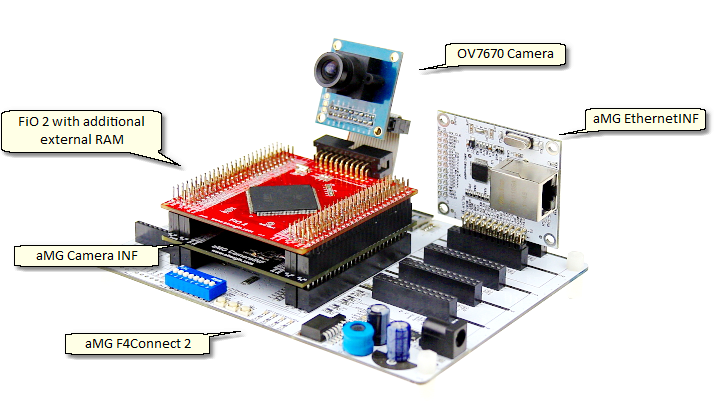
Hardware Setup
See DCMI Installation Guideline for instructions how to connect to connect to different version (1.1 and 1.2) of aMG CameraINF.
The following figure shows a Simulink model for the target. This model programs FiO 2 to acquire image data and send to the host PC via UDP protocol.
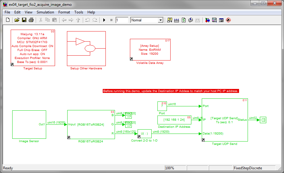
Target Model for image acquisition into Simulink in real-time.
The following figure shows Simulink model for the host PC. This model perform object tracking algorithm. In this way, it is very simple to visualize results, analyze performance, and tune the algorithm.
For background information on the algorithm visit http://aimagin.com/blog/basic-image-processing-object-tracking/
![]()
Track moving object from streaming video.
Stand-alone Application Test
In this step, the algorithm is moved to run in the FiO 2 board. The detected target XY positions are overlayed on the image using Simulation Computer Vision System Blockset. The resulting image is transmitted to the host PC to display in real-time (around 5Hz update rate). The following summarized necessary steps to make it work in real-time (compare with an ideal algorithm design running in pure Simulation simulation on the host PC).
- The Gaussian filter was not implemented. Since it put heavy computation load on the MCU.
- The XY position determination was redesigned to reduce execution time.
The following figure shows hardware setup.
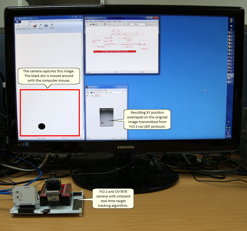
Hardware Setup
The following figure shows Simulink model for the target. The moving object tracking algorithm runs in FiO 2 in real-time.
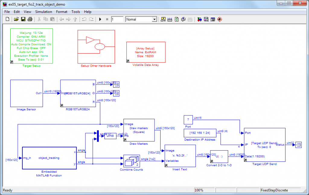
Simulink model file for FiO 2
The following figure shows the Simulink model running on the host PC. This model only receive image data and display on screen.
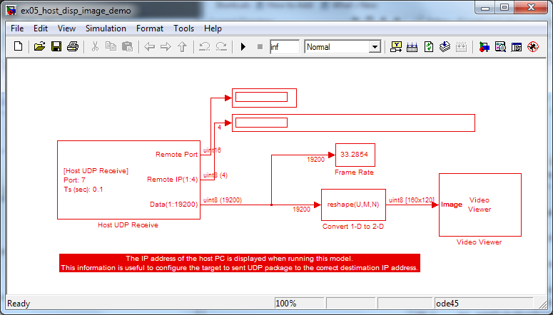
Simulink model file for the host PC
Note about using STM32F4DISCOVERY board with UDP Cam demo:
- At “Target Setup” block, double click to open Mask configuration. Select “STM32F4DISCOVERY Default (HSEOSC-8MHz/HCLK-168MHz)” for clock configuration option.
- Remove “FSMC_SRAM Setup” if any (may be located in “Setup Other Hardware” subsystem).
- At “Ethernet Link Setup”, change interface pins to “Profile #1”.