The Application of PWM Capture (Data Acquisition) and Ultrasonic Sensors
download all demo files: PWM_Capture_Demo1.7z
1 PWM Data Acquisition and Ultrasonic Sensor
1.1 Introduction
Pulse Width Modulation (PWM) applications can be found in number of applications for instance telecommunications, servo motor control, voltage regulation, power delivery and so on. This article describes how to measure the width of PWM using microcontroller? Furthermore, how ultrasonic sensor (which can be used for remote measurement) can work in conjunction with PWM.
1.2 HC-SR04
HC-SR04 is an ultrasonic sensor which can be used for remote measurement of physical quantities via ultrasonic waves. Human ear don’t have ability to detect ultrasonic waves. This module has an ability to detect a distance from 2 to 400 cm (1 to 156 inches) correctly and can be easily connected with the microcontroller. HC-SR04 has low power consumption which makes it suitable choice for robotic and automatic control systems.
The operating principle of ultrasonic sensor is the same as that of object detection system of a bat and is shown in Figure 1‑1. An ultrasonic transmitter sends a radio frequency of 40 KHz in the air at the speed of 346 meter per second and the receiver receives the reflected signal from the object. Distance between the transmitter and the object can be calculated by simple calculation by considering the time taken by the ultrasonic wave to travel from transmitter and received back (reflected) by the receiver. As speed of ultrasonic wave in air is fixed and known so distance (S) can be calculated by using the following equation.
S = 346 *0.5t .....................................................(1)
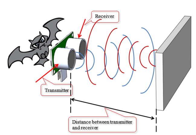
Figure 1-1: Principle of detecting object and measuring the distance between transmitter and the object of interest using sound waves
If the user is interested in calculating the distance between the object and the transmitter, the sensor module is configured so to do it. The result of the calculation is a pulse whose width is related to the measured distance.
1.3 The Active Module
This module has four pins and these pins are shown in Figure 1‑2. In the first experiment, which is very simple to do, consists of STM32F4DISCOVERY module along with the prototype board and some wire connections. Before the user starts the experiment, it is very important to understand the pin functionality of ultrasonic sensor [3].
- Up to 5V can be supplied to Vcc
- Trig is a pin input for a pulse width of 10 microseconds to regenerate 40 KHz frequency ultrasonic waves into the air from the transmitter.
- Pin 3 is the output pin for Echo pulse signal from the module to the microcontroller to detect the width of the pulse and calculate the distance.
- GND is the common point
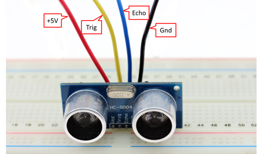
Figure 1-2: The use of ultrasonic module HC-SR04
The characteristics of this sensor is such that it generates a pulse signal with the width at which is least 10 µsec and is fed into the Trig pin. After waiting for 1.4 msec, it has pulse signal at Echo pin whose signal width is between 150 µsec to 25 msec. If width of signal is larger than the above range then it cannot detect object. Then it should delay about 10 ms and sends Trig signal again as shown in Figure 1‑3.
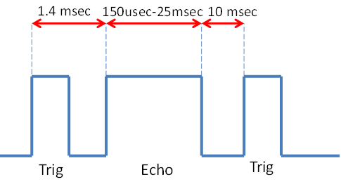
Figure 1‑3: Trig signal pin and Echo pin for ultrasonic sensor module
Following are the equations which can be used to calculate the distance between the transmitter and the detected object in cm and inches.
Distance (cm) = Width of Echo signal × 106/58..........................(2).
Distance (inch) = Width of Echo signal × 106/148......................(3).
1.4 Experiment 1
In this experiment, the basic functionality of the ultrasonic sensor is tested. We can say that this is a preliminary test of the sensor by reading data from the sensor and sending the information to the PC to display. Connection between the sensor module and aMG Lab Kit F4 is shown in Figure 1‑4.
The program in Figure 1‑5 have the same attributes as that of sensor attributes in Figure 1‑3 with the Trig signal width of 1ms and frequency of 27 Hz. Output PB7 of microcontroller blocks PWM capture which is used to measure the bandwidth of Echo signal that come from PB6 and send the data (that contain with bandwidth of Echo, % duty cycle of Echo, Trig frequency) to the PC using block USART.
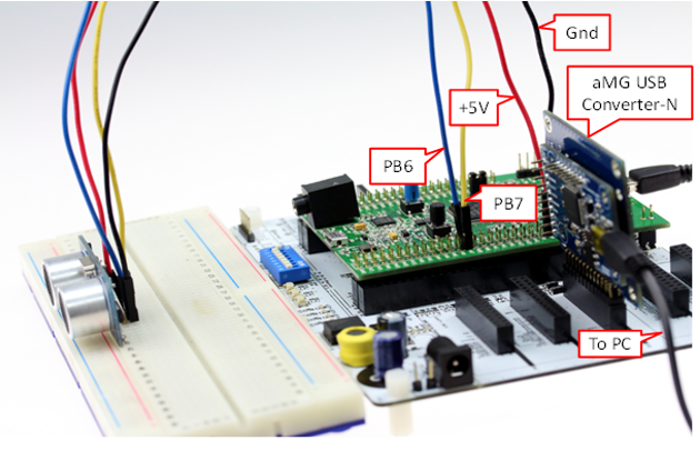
Figure 1‑4: Experiment with ultrasonic sensor and aMG Lab Kit F4
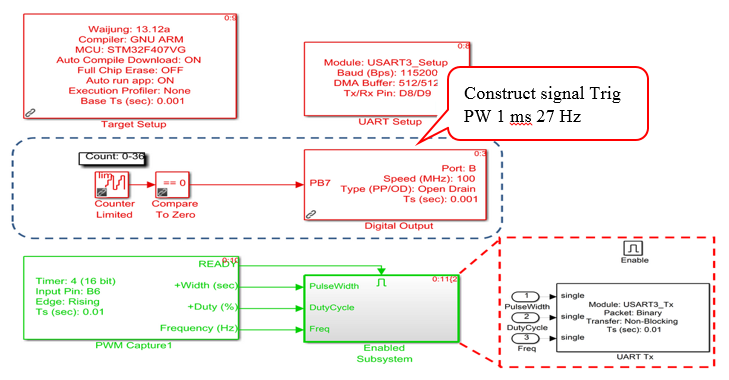
Figure 1‑5: Embedded in microcontrollers
This program gets data sent from the microcontroller as shown in Figure 1‑6. The signal is converted to a pulse width (units in µsec and then divided by 58) to get the distance in centimeters.
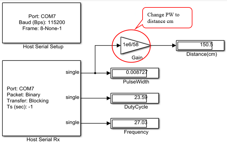
Figure 1‑6: Program on PC side
1.5 Experiment 2 – Testing the System Independently
The experiment will test the module separately. This can be applied to various projects such as robots, wireless monitoring and attaching LCD with it. Figure 1‑7 shows such experiment.
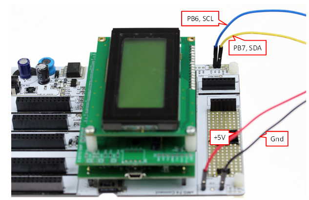
Figure 1‑7: Testing the module separately
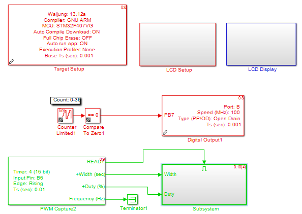
Figure 1-8: Embedded in microcontroller
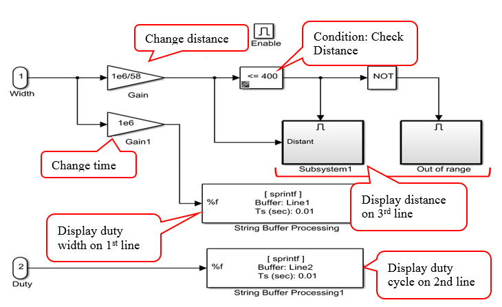
Figure 1-9: In subsystem
In Figure 1‑8 and Figure 1‑9, reliability of the sensor is tested. The results are satisfactory and such configuration can be used where high resolution is not required.
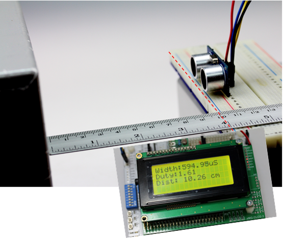
Figure 1‑10: To test the reliability of sensor
2 Summary
In this article, examples have been presented in which PWM capture block measures the width of the pulse. For example, remotly measuring of distance between transmitter and point of object can be found using ultrasonic sensor in conjunction with aMG Lab Kit F4. Furthermore, the standalone ultrasonic sensor has been tested as well. This document gives a good background for those who are interested some advanced experimentation in this domain.
3 References
[1]. HC-SR04 User Guide> http://www.elecfreaks.com/store/download/product/Sensor/HC-SR04/ HC-SR04_Ultrasonic_Module_User_Guide.pdf
[2]. Product User’s Manual – HC-SR04 Ultrasonic Sensor> https://docs.google.com/document/d/ 1Y-yZnNhMYy7rwhAgyL_pfa39RsB-x2qR4vP8saG73rE/edit
[3] STM32F401xD, STM32F401xE Data Sheet> http://www.st.com/st-web-ui/static/active/en/ resource/technical/document/datasheet/DM00102