The Applications of Global Positioning System
Download demo file GPS_waijung_demo.7z
1 The Applications of Global Positioning System
1.1 Introduction
Many people have benefited from the Global Positioning System (GPS) receiver especially while using smart phones. The most adopted application of GPS is navigation for the car and tracking of commercial vehicles. Due to recent advancements in the domain of solid state devices, the GPS device is getting smaller (which can fit in smart phones conveniently) and are cheap. For these reasons, people have access to this technology easily. The applications for GPS are quite attractive and is useful in everyday life matters. GPS system can provide the exact location of the user almost everywhere in the world at any given time and all this service is free of charge.
1.2 Principles
GPS [6] refers to the GPS system of the satellites located above the earth surface. This radio-navigation system is formed from the constellation of 24 satellites and their ground stations which are shown in Figure 1‑1. The basis of GPS is triangulation from the satellites. To triangulate, a GPS receiver measures the distance using travel time for the propagation of radio waves. The current GPS system which everyone is using is deployed by United States. Russia has also joined the race and have a navigation system named GLONASS system. Galileo system is from EU with China, Israel, India, Morocco, Saudi Arabia South Korea and Ukraine. Beidou system is deployed by Chinese and QASS system is deployed by Japanese.
The most common name for GPS satellites is NAVSTAR and these satellites were manufactured by Rockwell International. The altitude of these satellites is 10,900 nautical miles and the orbital period is 12 hours. All the satellites have very precise atomic clock on board however atomic clock cannot be built in the GPS receiver for economic reasons. All the GPS receivers are synchronized with Universal Time (UT). To overcome the need for the atomic clock, at least four satellites are required to determine the position of the receiver used for X, Y, Z and time error correction.
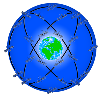
Figure 1-1: Position and orbits of GPS satellites around the world
1.3 GPS Receiver
GPS receivers are available in the market easily. There are many manufacturers for GPS receivers. GPS receiver can be used immediately by the individuals such as GPS in mobile phone. The discussion on series of small modules for the developers will be done in later section but first it is very essential to know the various definitions for the GPS module.
- Accuracy – accuracy refers to the correctness in measuring the position of the receiver on the ground. The accuracy of the receiver which has an affordable price has a reasonable accuracy of + 3 to 5 meters [7]. In case the user is looking for more accuracy then DGPS [5] or RTK GPS [13] are better choices. GPS works well for outdoor environment with a clear view of the sky.
- Antenna – antenna tuner. As the satellites are 12,000 miles away from the receiver, the signal strength from the satellite becomes very weak as they reaches the ground. Therefore the tuner must be highly efficient. There are various types of antenna available in the market and few of them will be discussed now.
- Patch Antenna – Patch antennas are the most favorable choice for the customers as they are quite compact in size and no need for additional antenna. Furthermore patch antennas are easy to use [1]. Patch antenna is shown in Figure 1‑2
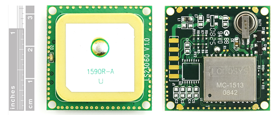
Figure 1‑2: GPS module patch antenna types - GPS module with Helical Antenna – these modules are larger than patch antenna. It requires more antenna to have better signal reception in all directions and helical antenna is shown in Figure 1‑3.

Figure 1-3: GPS module with helical antenna - GPS module with External Antenna. This type of antenna have reverse SMA connector which can be connected to an external antenna as shown in Figure 1‑4. In case the antenna is not connected then it is not a suitable choice for inside building or vehicle installation.
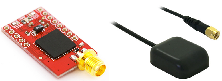
Figure 1-4: External GPS antenna type module
- Patch Antenna – Patch antennas are the most favorable choice for the customers as they are quite compact in size and no need for additional antenna. Furthermore patch antennas are easy to use [1]. Patch antenna is shown in Figure 1‑2
- Baud Rate – Baud rate is synonymous to symbols per second. A baud rate of typical communication patterns in the data from GPS receiver to a serial (UART) is 9600 bps, 57600 bps etc. Exact values can be known from the datasheet of the GPS receiver.
- Channel – Channel represents the number of channels of the receiver which actually reflects the capabilities of tracking the number of satellites. For example, if the receiver has 12 channels it means that it has a capability of tracking 12 satellites simultaneously. The more channel helps user to determine the position in shorter time but at complex hardware cost. However it is recommended to switch off some channels to save energy.
- TTFF (Time to First Fix) – refers to the time from startup to be able to calculate the correct position. It would require data from at least four satellites. TTFF time is also dependent on weather conditions.
- Lock & Fix – means to locate and track the position of the satellite. If user gets a satellite signal from 4 satellites before they are processed for accurate position and time.
- Start-up Times (Hot, Warn and Cold) – it takes some times to lock on by a GPS receiver especially when the receiver is moving. The time required to lock the GPS receiver depends how the GSP receiver starts which has three conditions i.e. Hot, Warm and Cold. Hot start means the GPS device remembers the last calculated position and view of satellites. Based on the previous information, new position is calculated and is the quickest method. Warm start means when GPD device remembers the last calculated position but don’t remember the satellite view. Cold start refers when GPS device attempts to locate satellite and calculates a GPS lock. This is the most sluggish method.
- Update Rate – refers to the frequency of the position of the modules (in Hz) which is typically around 1 per second or 1 Hz. However higher update rates (5 Hz, 10 Hz) creates a better and higher resolution vehicle tracking capabilities.
2 Experimenting GPS Module
After understanding the basic principle of GPS system, in this section some experimentation will be done for GPS module LOCOSYS Model LS20031 [1] which is shown in Figure 2‑1. This module is easily available in the market at affordable price. This module have an embedded antenna and GPS receiver circuits. The GPS smart antenna will track up to 66 satellites at a time while providing fast time-to-first fix. LS20031 has Built-in micro battery to preserve system data for rapid satellite acquisition. Other features of this module includes 5 Hz output, 57600 bps TTL serial interface, 3.3V @ 41 mA output, fast TTFF at low signal level and LED indicator for fix and no fix [8] [9].
2.1 Hardware
This is a right angle pin header soldered on the PCB board. It can be used with proto-board. Pins and function of each pin of the GPS module is shown in Figure 2‑1.
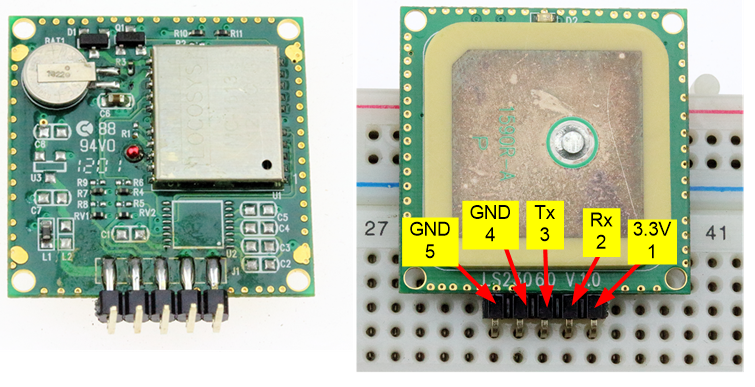
Figure 2-1: GPS module and pin position
2.2 Initial Testing
To ensure that the purchased module is working, there is a simple test by connecting the module to the PC. The equipment needed for this testing is shown in Figure 2‑2 which includes aMG USB Converter N2 [2].
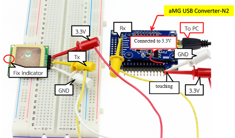
Figure 2-2: Circuit for testing the performance of GPS module with PC
For normal usage, if we only read data from the module it is not necessary to connect with GPS Rx pin. But if user want to have some specific configuration i.e. setting baud rate etc. in that case we need to connect it with GPS Rx pin.
After completing the circuit and plugging the USB cable to the PC, if the PC asks for driver aMG USB Converter-N2, these drivers can be downloaded from [14] which can be used to receive and display the GPS data on the PC. User can use standard software for communication such as UART Putty [12] or MiniGPS [10].
2.3 Using Putty
This program works well and is freeware. After installing the driver aMG USB Converter-N2, user need to check port using Device Manager and then open the Putty program and assign the values as shown in Figure 2‑3. If no errors are displayed then user need to wait for about 30 to 60 seconds for the search module and lock the position of the satellite. Note that the Position Fix Indicator LED flashes every second which indicates the module is ready for use and displays the data as shown in Figure 2‑4.
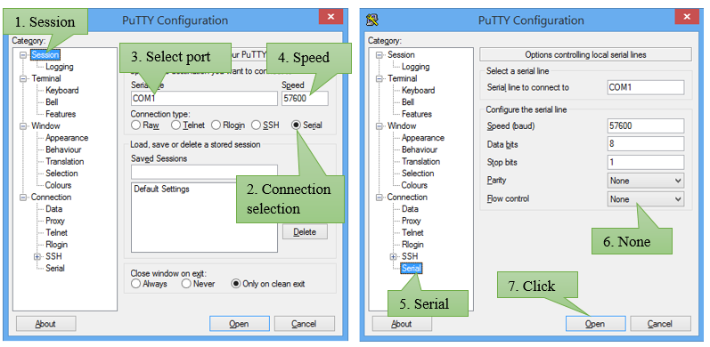
Figure 2-3: The configuration of communication Putty

Figure 2-4: Information about from GPS
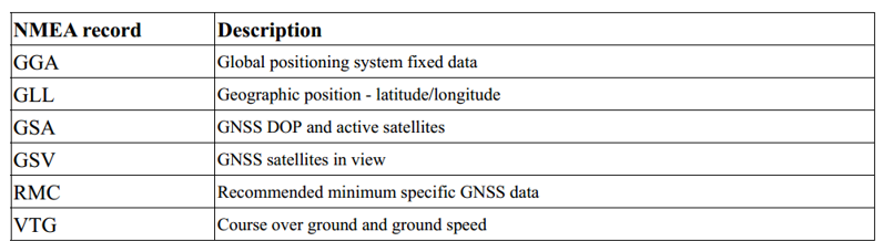
GPS is based on National Marine Electronics Association (NMEA) and the characters begin with $ GPxxx which has 6 types namely GGA, GLL, GSA, GSV, RMC and VTG. VTG. These abbreviations are described in Table 2‑1 .
$GPGGA,053740.000,2503.6319,N,12136.0099,E,1.1,63.8,M,15.2,M,,0000*64
The above line data refers to a data model GGA or Global Positioning System fixed data followed by UTC time coordinates for latitude of the hemisphere and the coordinates of longitude for the hemisphere and the remaining part is to write a program to retrieve the desired position. It is important to know the meaning of each position which has been discussed in detail in reference [8] [9].
Table 2-1: NMEA record and their description
2.4 Reading from MiniGPS
The method for setting the baud rate and port for the PC for MiniGPS is the similar as that of Putty. Figure 2‑5 and Figure 2‑6 describes the configuration of MiniGPS and setup of GPS module with MiniGPS.

Figure 2-5: Configuring MiniGPS
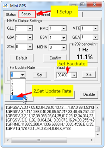
Figure 2-6: The setup of GPS module with Mini GPS
3 Experimenting with Actual Microcontroller
After the user makes sure that the simulation is working fine, the next step is to buy the required module for doing some experimentation. In the experiment described below, a microcontroller board aMG Lab Kit-F4 will be used and is shown in Figure 3‑1. The microcontroller will read the GPS data and then the data will be sent to PC.
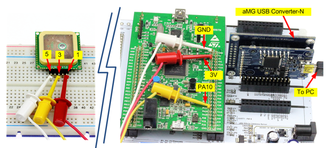
Figure 3-1: Reading GPS data through a mircocontroller aMG Lab Kit F-4
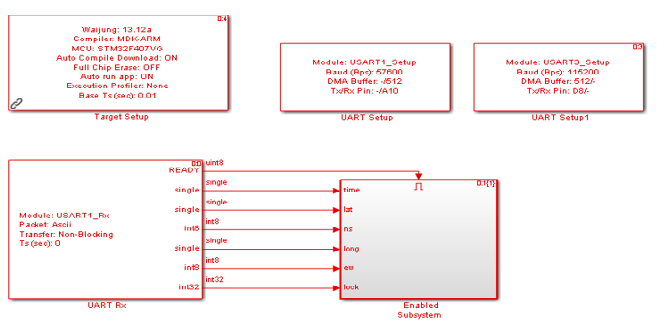
Figure 3-2: The firmware application in microcontroller
The firmware application of the microcontroller is based on USART1 module as shown in Figure 3‑2. A GPS with baud rate of 57600 bps and UART3 interfacing with PC with baud rate of 115200 bps. Setting parameters of UART RX module given by Transfer to Non-Blocking letting Ready signal invokes the Subsystem. That means data must be received before send them to Pack mode, select data representation as ASCII.
$GPGGA,%f,%f,%c,%f,%c,%d’ represents the choice of the data with a header as GGA along with 6 other sequences which are UTC time, Latitude, N/S Indicator, Longitude, E/W Indicator and Position Fix Indicator in sequence. If user need to read more than 6 parameters, then simply format the string specifiers like %e, %f, %g etc. depending upon which type of information that finally determines the end of package (CRLF) and is described in Table 3‑1
Table 3‑1: The alignment of GGA

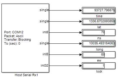
Figure 3-3: The program on PC side
The program that supports sending values from the microcontroller is shown in Figure 3‑3. When the loading of downloaded firmware is complete, verification of port number is required. In the mentioned example, COM12 is used and set to have a baud rate of 115200 bps to match the data obtained from the raw data that have not been synthesized and hard to read. In this example, demonstration is given how to communicate and retrieve the information which user need to use.
3.1 Experimental Data for Receiving Data from GPS
When the data communication between the GPS and PC is complete, the next step is to customize the received data. Figure shows the details.
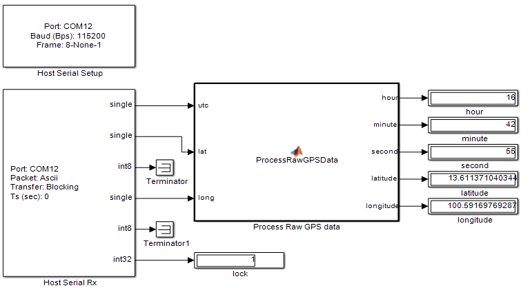
Figure 3-4: The program on PC side
3.2 Experimental data of RMC
This experiment will change the reading data from GGA to RMC. The converter data can be applied to motor control system. Details regarding model information can be found in [8]. The firmware applications in microcontroller can be seen in Figure 3‑5 and the program which can be used at PC side is shown in Figure 3‑6.
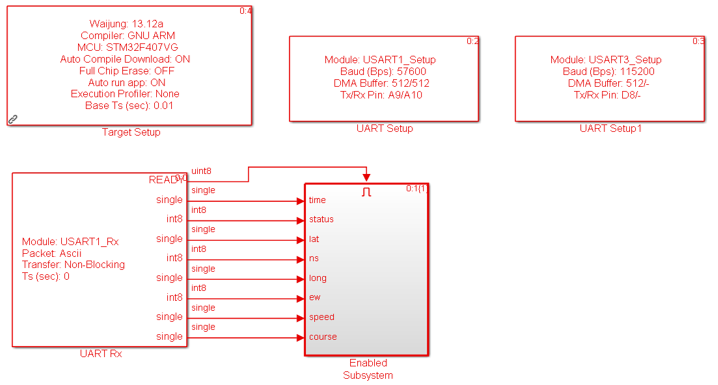
Figure 3-5: The firmware application in the microcontroller
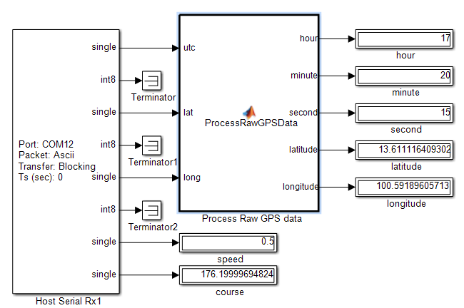
Figure 3-6: The program on PC side
4 Some More Experiments
4.1 Standalone GPS System
This experiment is to create a system that can work standalone without using a PC therefore some external hardware is needed to display the values. A 16 character, 4 line LCD is shown in Figure 4‑1 and updated firmware is shown in Figure 4‑2.
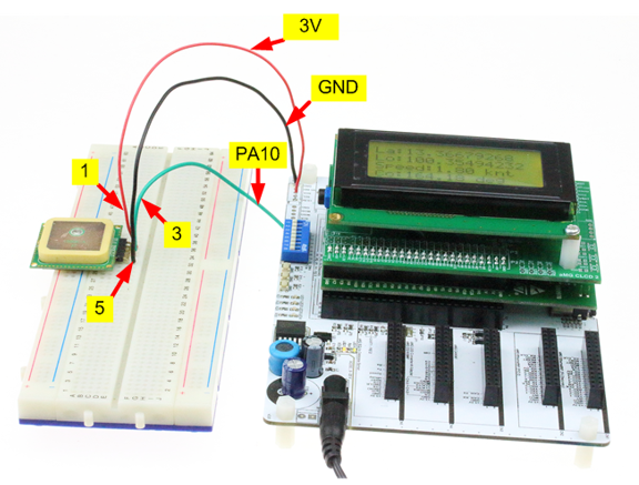
Figure 4-1: Experimenting standalone GPS
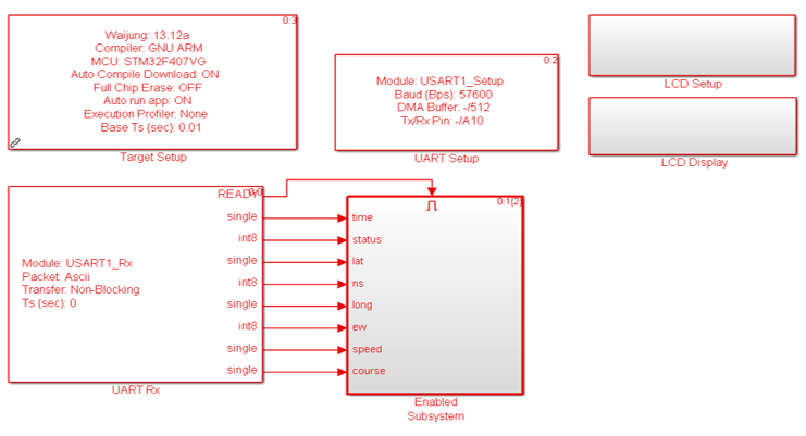
Figure 4-2: Updated firmware for standalone GPS
If there is no error then microcontroller can receive different values from GPS and these values will be displayed on LCD with 4 lines. The results are shown in Figure 4‑3.

Figure 4-3: Display of standalone GPS
4.2 An automated Vehicle Control Project
This experiment gives an example of the case that user need to program the “automatic drone” to move from the current position (Home) to the position as per Figure 4‑4. The automatic drone will get the current position from the GPS and then calculate the direction (or bearing) and the distance to the target position.
Calculation of direction (three digits in unit of degree from 000 – 359, where 000 is North). For the distance, if two geographical locations are away i.e more than 20 kilometers (or 12 miles), we need Haversine equation [3-4] which uses the principle of spherical trigonometry since the curve of the Earth is also related. However, for the shorter distance (less than 12 miles), we can simply calculate with trigonometry on a plane and use Pythagoras theorem to find the nearly exact position. However, firstly, we will have to transform distances of two positions which are latitude and longitude coordinates to Cartesian coordinate using Equirectangular Approximation [3-4].
The example position given is less than 13 latitude degree north resulting in lower effect of the curve of the Earth, therefore, we just need to transform longitude to the plane and in order to find the Equirectangular approximation value we use the following equations.

where x is the distance on the horizontal axis which is equal to the difference between the average of latitude and longitude multiplied by cos
y is the distance on vertical axis which is equal to the difference of Latitude

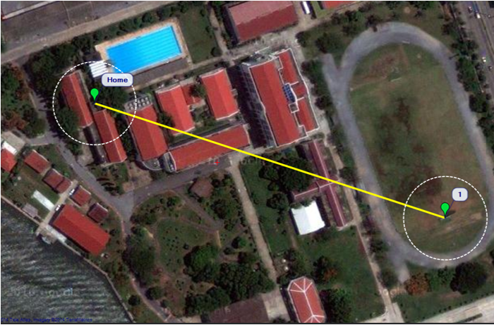
Figure 4-4: Finding bearing and distance between two pair of latitude and longitude position on the Earth surface
When we know the distance on the plane then we calculate direction angle and distance from tangent equation using Pythagoras theorem as follows.
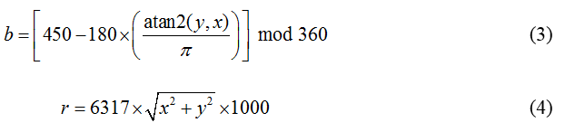
where b is direction from the drone to the assigned location
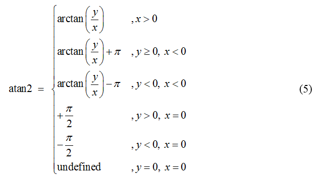
atan2 is a function giving value in radian with condition depending on the values of x and y as follows;
- m mod is a function giving the remainder of
- is the distance from the drone to the assigned location in meter
- The constant 6371 is earth radius
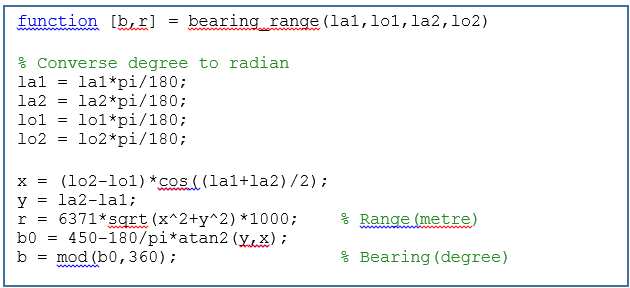
- The constant 450 means, normally we measure angle in counter clock wise from position 0,0 at axis but to measure bearing, we move position 0,0 to y axis then measure angle in clock wise. Therefore, at position 0,0 at axis is 360+90 = 450 degree. All the equations mentioned can be written in MATLAB program as follows.
After direction and distance were calculated, we use the results to turn the drone to the assigned direction and then move regarding to the calculated distance.
Programming Firmware of the microcontroller shown in Figure 4‑5 and the PC programming is shown in Figure 4‑6. Algorithms for the calculation of the bearing and the distance are in MATLAB function boxes.
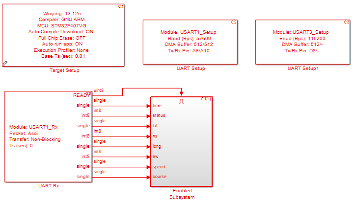
Figure 4-5: Firmware programming in microcontroller

Figure 4-6: The program on PC side
Figure 4‑7 is the test of algorithm using Mission Planner [11] which is famous for the DIY Drones developers. We assigned distance between two position in the map and the calculated direction angle which turns out to be 108 degree, the distance of 265.21 meters. For our self-developed program, the calculated angle is about 108 degree and the calculated distance is about 260.14, thus the accuracy of our program is acceptable.
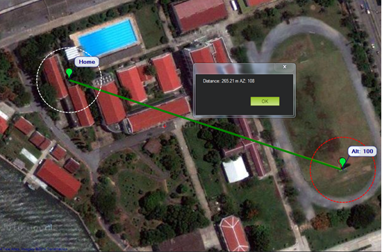
Figure 4-7: Calculated results from Mission Planner program
5 References
[1] 66 Channel LS20031 GPS 5Hz Receiver, http://www.thaieasyelec.com/index.php?lay=show &ac =cat_show_pro_detail&pid=51241
[2] Aimagin Products: https://www.aimagin.com/index.php/products.html
[3] Bob Chamberlain, “What is the best way to calculate the distance between 2 points?”, http://www.cs.nyu.edu/visual/home/proj/tiger/gisfaq.html
[4] Chris Veness, “Calculate distance, bearing and more between Latitude/Longitude points”,http://www.movable-type.co.uk/scripts/latlong.htm
[5] Differential GPS, http://en.wikipedia.org/wiki/Differential_GPS
[6] Global Positioning System, http://en.wikipedia.org/wiki/Gps#cite_note-2
[7] How Does GPS Work, https://learn.sparkfun.com/tutorials/gps-basics/how-does-gps-work
[8] Locosys LS20030-3 GPS Module Datasheet, https://www.sparkfun.com/datasheets/GPS/ Modules/LS20030~3_datasheet_v1.2.pdf
[9] LS20030~3 GPS Smart Antenna, http://www.locosystech.com/ product.php?zln=en&id=20
[10] MiniGPS Software Download, http://www.sparkfun.com/datasheets/GPS/MiniGPS_1.32.zip
[11] Mission Planner Software download, http://ardupilot.com/downloads/
[12] PuTTY Download Page, http://www.chiark.greenend.org.uk/~sgtatham/putty/download.html
[13] Real Time Kinematic (RTK) satellite navigation, http://en.wikipedia.org/wiki/Real_Time_ Kinematic
[14] Virtual COM Port Drivers, http://www.ftdichip.com/Drivers/VCP.htm