Using Hardware in the Loop with Waijung
1 Using Hardware in the Loop with Waijung
Hardware-in-the-loop (HIL) simulation is a technique for performing system-level testing of embedded systems in a comprehensive, cost-effective, and repeatable manner [1].
1.1 Introduction
While developing a practical embedded system such as fuel control system in a vehicle i.e. Engine Control Unit (ECU), the developer needs time to design and test system with real vehicle and test the outcome of the system by putting the model in real situations for example what happens if the sensor is malfunctioning/stop working as well as find any possible errors of program. All this testing is to make sure that the system is reliable and the system can handle the problems which could happen. Only then the system/product can be put into commercial use.
The testing period is the most costly time period because the testing equipment is very expensive and it takes a lot of time to analyze the information. It is challenging to reduce the cost and the testing time while still keeping the efficiency of the testing.
The modeling system, Hardware In the Loop (HIL), is one of the most useful technique to design and test embedded system because it covers all the possible situations which can happen and the testing can be repeated many times. This modeling system must be modeled at the real time and must be connected with embedded system that we need to test i.e. embedded system under test (SUT) [1] as shown in Figure 1‑1.
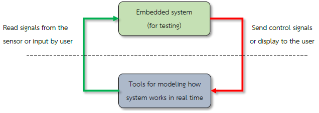
Figure 1-1: General characteristics of simulation of HIL
HIL simulation principles can be applied in a number of applications. From the simple applications, such as temperature control systems, the speed of the electric motor to more complex systems such as robotic arms control system or automatic flight of the aircraft and so on.
1.2 Why to use Matlab with HIL test
- Matlab is a mathematical analysis and engineering design tool which has a complete, user-friendly and interactive environment and with the help of Simulink, mathematical modeling of simple as well as complex systems can be done with great ease.
- Mathematical models created with Matlab Simulink Toolbox can be easily set up and changes in the models can also be made very easily. Developers can observe the response of the model without programming. It enables developers to quickly design a complete end to end system and observe its response.
- Using Matlab with HIL test for specific tasks such as test flight control system, which is a complex and difficult test can be done quickly. Such systems need to be designed very carefully as it has a direct impact with the lives of the human beings. Simulink provides an opportunity to test the system rigorously before actually deploying the system.
1.3 Modeling Speed Control System for a Motor
Aim
- To allow the users to create a model of a continuous and discrete time control of the system;
- To compare the results of the simulation from a Continuous-time control of the system with Discrete-time control of the system.
This is an example of modeling of system which controls the speed of rotation of the motor in which a mathematical model reflects the relation between PWM Duty Cycle and the speed of the motor.
The control system of an embedded system need to use discrete-time in which the sample time of the system will have effect on the calculation of the variables of controlling system and the outcome of the modeling system.
Use of Matlab Simulink toolbox allows the development of control system models for embedded systems. After simulating the environment, the discrete time simulation results are compared with the continuous time.
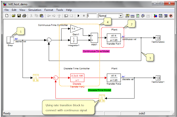
Figure 1-2: Simulink Model for the speed control of the motor spindle
Figure 1‑2 shows the simulation model for speed control of the motor spindle. The functionality is described as below.
- Step block used to configure the desired motor spindle speed (Desired vel), which is equal to 700.
- Modeling the electric motor – transfer function block (a Continuous-time). The input to this transfer function is the PWM duty cycle and the output signal is the speed of the motor’s spindle.
- The spindle speed signal is fed back to compare with the Desired vel and then sent to the control system to adjust the voltage accordingly.
- The control system is Continuous-Time PI Controller and Discrete-Time PI Controller which works with Sample time of 0.005 seconds.
1.3.1 System Simulation Settings
Go to Simulation Configuration Parameters menu or press Ctrl + E. Configuration Parameters window will appear as shown in Figure 1‑3.
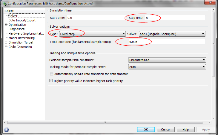
Figure 1-3: The system simulation
Other parameters should be set as follows.
- Stop time: 5 to set the duration of the simulation for 5 seconds.
- Solver Option type: Fixed-step for the simulation of model sample time constant.
- Fixed-step size: 0.005 to configure Sample time.
1.3.2 Simulation Results
When Run Simulation icon is clicked, response of the motor for both continuous-time controller and discrete-time controller can be seen as in Figure 1‑4.
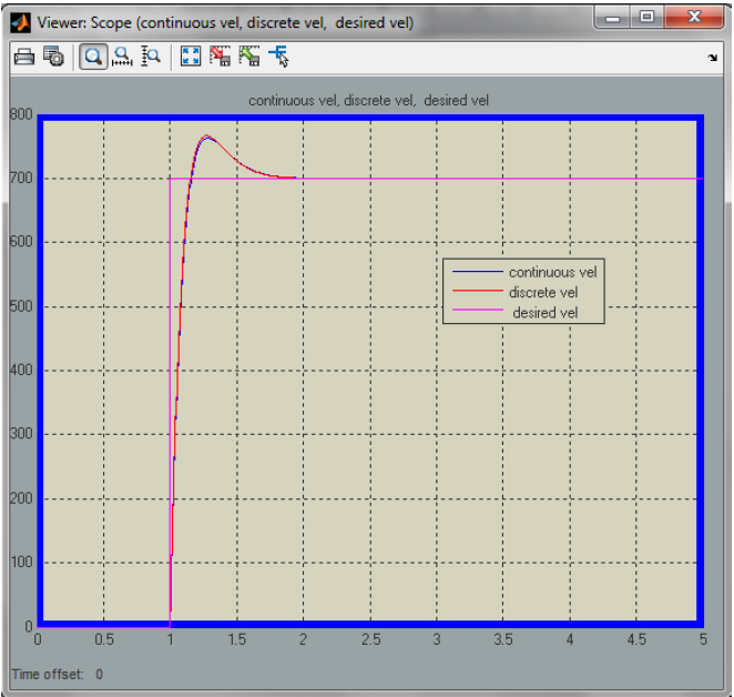
Figure 1-4: Simulation results of spindle motor speed control
2 Example for Hardware in the Loop
Waijung Blockset for the Hardware in the Loop (HIL) simulation examples are 3 of types depending on the application which are described as follows.
- Discrete-Time Algorithm in host PC – Plant in target, testing algorithm with more complex applications or from the Host Controller
- Discrete-Time Algorithm in target – Plant in host PC, testing algorithm for the desired application in embedded systems.
- Discrete-Time Algorithm in target Continuous-Time Plant in host PC, testing algorithm for the desired application in embedded systems as well.
2.1 Equipment Used in the Experiment
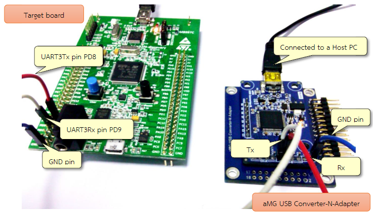
Figure 2-1: Devices used in Hardware In the Loop (HIL)
Figure 2‑1 shows the equipment used in this experiment for Hardware in the Loop which consists of STM32F4DISCOVERY board, a target board and aMG USB Converter-N-Adapter for high speed data transfer.
2.2 Setting up Communication in UART Host and Target
To get the most effective results of the simulation, users should set the Host Serial Block (in the host model) and UART Rx / Tx Block (in the target model). Based on the type of HIL, characteristics of Host PC and target are given in Table 2‑1.
Table 2-1: Serial Block on Host PC board and the target
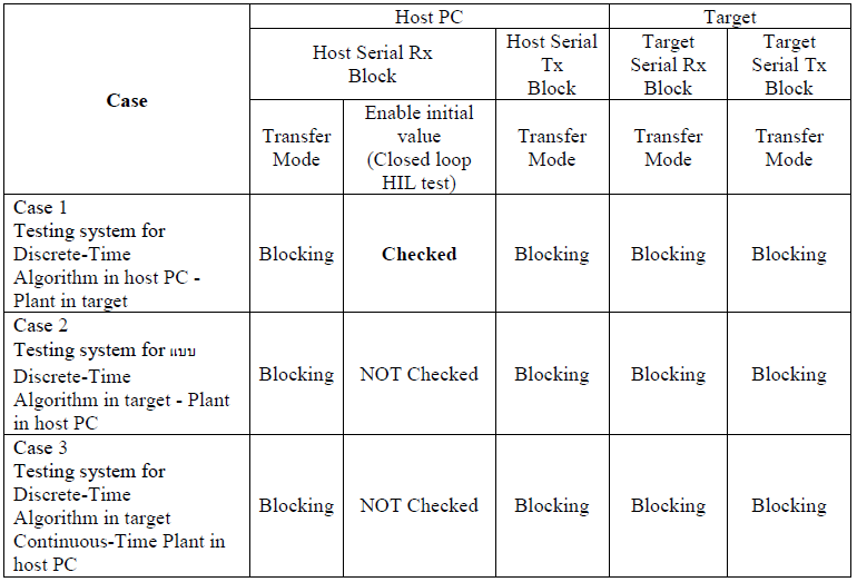
After enabling the initial value (Closed loop HIL test), the host will send the information to the target at the start of the simulation. This ensures that the data transfer between host and target can pick the correct setting as shown in the Case 1 of Table 2‑1. In addition, the user must manually reset Target board before testing in HIL.
In addition, the user must define the format for the data transmission between Host and Target for synchronization. Binary data format is recommended for high speed data transfer. If the computer does not receive data from the target board, then error message will be displayed as shown in Figure 2‑2 when Run Host Model.
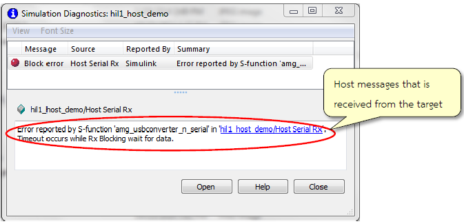
Figure 2-2: Host model message if the computer cannot receive information from target board
2.3 Case 1: Testing System with Discrete-Time Algorithm in host PC – Plant in target.
Simulation of Discrete-Time Algorithm in host PC – Plant in target can be represented as shown in Figure 2‑3.
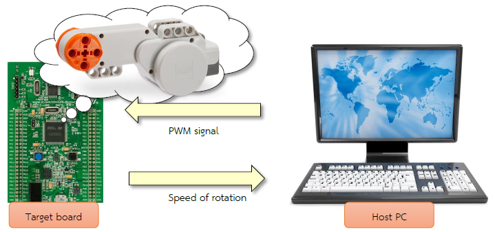
Figure 2-3: Simulation of Discrete-Time Algorithm in host PC – Plant in target
Download the Simulink model as shown in Figure 2‑4 on STM32F4DISCOVERY. In this example, the plant is a motor.
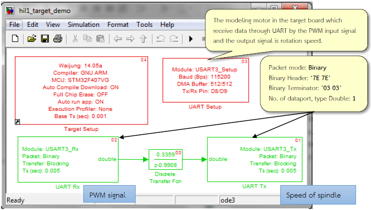
Figure 2-4: Simulink model for motor at Target board
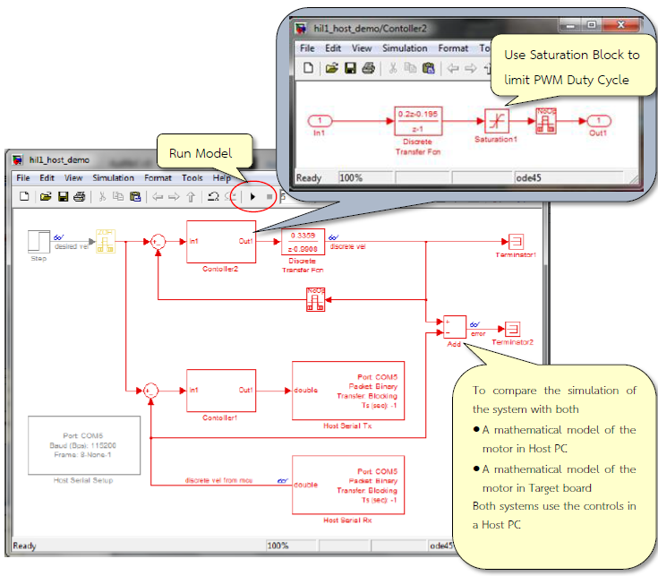
Figure 2-5: Simulink model to control the spindle speed in the Host
Figure 2‑5 provides a comparison between discrete-time mathematical model of the motor in the Host PC and discrete-time mathematical model of the motor in the target board by algorithm of speed controls in the Host PC.
When Run Host PC, results are shown in Figure 2‑6 (double click on search icon)
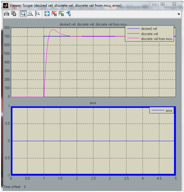
Figure 2-6: The simulation results for speed control of motor’s spindle (Case 1)
2.4 Case 2: Testing System with Discrete-Time Algorithm in target- Plant in host
This example shows the speed controlling system in the target board by giving a mathematical modelling of the motor in the host PC as shown in Figure 2-7.
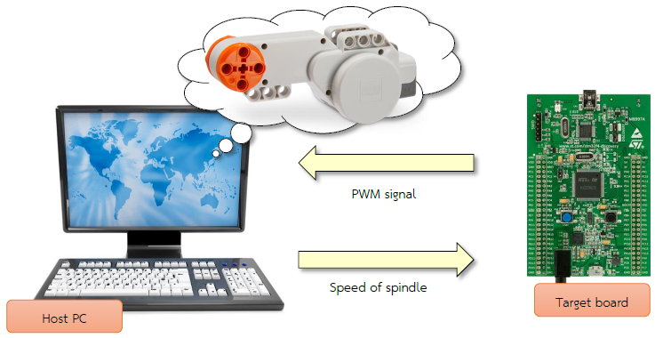
Figure 2-7: Simulation model for Discrete-Time Algorithm in target – Plant in host
Download the Simulink model on STM32F4DISCOVERY board as shown in Figure 2-4. This model is the controlling system of the motor which receives the desired speed (Set point) and the speed from the modeling (Process Variable) through UART Rx Block and send the instruction (PWM duty cycle) through UART Tx Block.
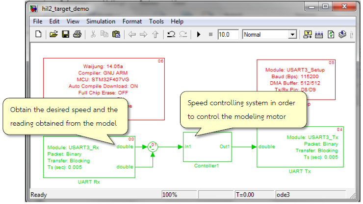
Figure 2-8: Simulink model to control the speed of the motor in the target
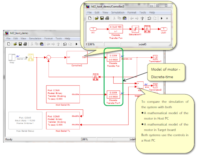
Figure 2-9: Simulink model for motor speed control in the host
Figure 2‑9 shows the simulation model framework in comparison with a mathematical model of the motor. Discrete-Time Algorithm for speed control in the Host by the Host PC (Discrete-time in the Host PC with a mathematical model of the motor) is shown in Figure 2-10.
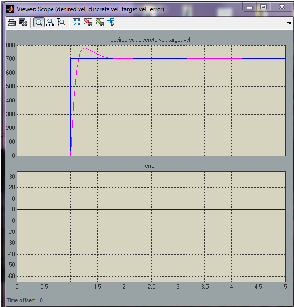
Figure 2-10: Results of the spindle motor speed control (Case 2)
2.5 Case 3: Testing System with Discrete-Time Algorithm in target – Continuous-Time Plant in host
This simulation model is similar to the simulation model for the Case 2 but the mathematical model of the motor in the host PC is changed to continuous time from the discrete time and is shown Figure 2‑11. Algorithm for speed control in the target is shown in Figure 2‑8.
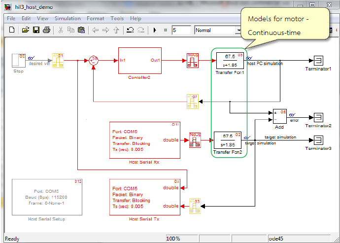
Figure 2-11: Simulink model for speed control of motor in continuous time at Host PC
So the modeling system will give comparative results between the speed controlling system which has algorithm in the target board and algorithm in the host PC. Mathematical modeling of the motor for continuous time in the host PC we give the result as in Figure 2-12.
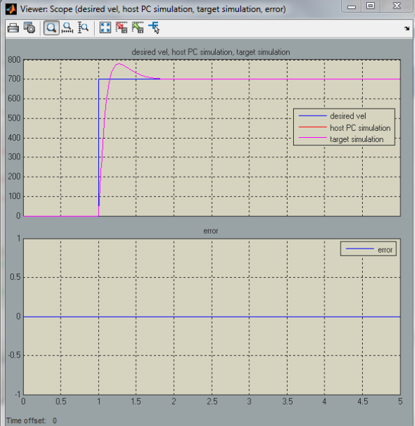
Figure 2-12: Results of the spindle motor speed control (Case 3)
Note: the user should press re-set button on the target board every time before Run Simulation Model.
3 References
- Ledin, Jim A. “Hardware-in-the-loop simulation,” Embedded Systems Programming, vol 12, 42-62, 1999.
- http://waijung.aimagin.com/index.htm?hardware_in_the_loop_tests_demo.htm
- http://waijung.aimagin.com/amg_usbconverter_n2.htm