Using TimerCounter
download all demo files: Timer.7z
1 Using Timer / Counter
All microcontrollers have a clock which helps them in executing the programs in a rhyming way. Clock is actually a digital signal with high frequency and set the pace of inbound and outbound data bus processes. Depending on the clock speed, the processing of microcontroller can be fast or slow (STM21F4DISCOVERY can operate up to 168 MHz frequency).
The clock of the microcontroller can be used in several modules such as analog to digital module, serial communications module, synchronous and asynchronous timers.
Microcontroller timer modules can be used in many applications such as time delay, creating a periodic signals (PWM), signal detection (input capture) etc.
Important components of the timer module are as follows.
- Counter register is a 16 bit integer data type. When there is a raising edge or an external signal on the pin of the timer, the counter will incur the count process.
- Up Counter will start counting from 0 to a preset value. When the preset value is reached, the counter will again start counting from 0 to the same preset value and this process keep on going.
- The Down Counter will start counting from a preset value to 0 and this process also keeps on going like Up Counter.
- Up-Down counter will start counting process from 0 to a preset value. When preset value is reached, it will start counting down from preset value to 0.
- A prescaler divider is an electronic counter circuit which is used to reduce a high frequency electrical signal to a lower frequency electrical signal by integer division. The user can select a value from 0 to 65535 as a divisor function. Prescaler is shows as in Figure 1‑1.
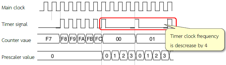
Figure 1‑1: Operation of timer/counter when the Prescaler is changed from 1 to 4 [1, p. 296]
In STM32F4DISCOVERY, there are 17 modules which are associated with the clock signal and can be set by 14 Timer series modules (TIM1 to TIM14), where each module is shown in Table 1-1.
Table 1‑1: Timer modules [2, p. 30]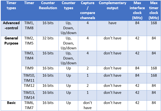
From the Table 1‑1, it can be seen that the STM32F4DISCOVERY timer modules can have a variety of settings. Users have to study the related settings of the registers, prescaler configurations and their limitations. Timer module in Waijung Blockset in the TIM library can reduce the effect required to understand the settings of the registers, prescaler and can enable them to develop applications more quickly.
2 Using PWM signals
2.1 Introduction
Pulse Width Modulation (PWM) is a periodic signal with a fixed frequency. User need to adjust the width of the pulse (i.e. the time for which the pulse is ON). Consecutive ON and OFF in a pulse is known as the duty cycle which can be calculated by the following equations.
Duty cycle (%) = (tON x 100) / Period
= (tON x 100) / (tON + tOFF)
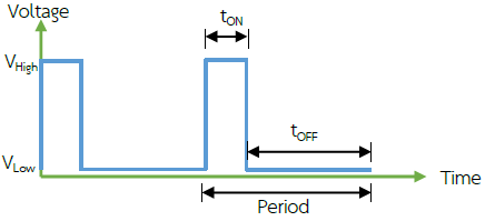
Figure 2‑1: PWM duty cycle
PWM signal is commonly used to control devices such as speed of DC motor or brightness of the bulb. The advantages of PWM signal are: reduces energy loss due to constant stimulation and can be connected to a microcontroller which can further be connected to the computer and give power to the device. Duty cycle adjustment is easy to make. Furthermore, the PWM signal is used to send commands to devices such as RC servo motor and so on.
Adjustment in the width of the pulse can be achieved by comparing the two signals. The first signal is a triangular signal which is compared with the signal with desired pulse width (reference signal).
In STM32F4DISCOVERY, using counter value of the timer module, triangular signals with a constant frequency can be generated which can then be compared with the reference signal. If the value of the counter is less than the reference signal value then the status of the output signal is set to ON state. If the value of the counter is more than the reference signal values then output is set to be OFF and is also shown in Figure 2‑2. Such kind of duty cycle adjustment is knows as Edge aligned mode [1, p. 315].
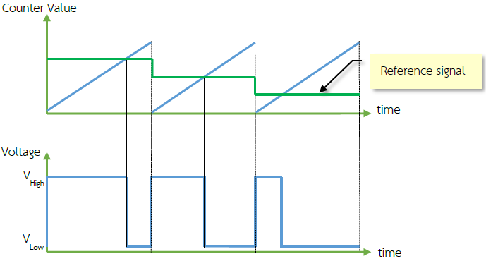
Figure 2‑2: Duty Cycle of a PWM signal to adjust the Edge aligned mode
Also STM32F4DISCOVERY have a duty cycle in center aligned mode which is shown in Figure 2‑3 by replacing the triangle (the Up-Down Counter) [1, p. 316].
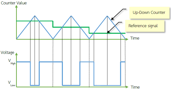
Figure 2‑3: Adjusting the duty cycle of a PWM signal in center aligned mode
2.2 How to use Basic PWM Block
There is a basic PWM Block in Simulink library >> Waijung Blockset >> STM32F4 target >> On Peripheral Chip >> TIM with the following characteristics.
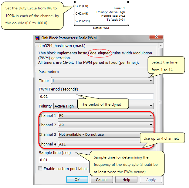
Figure 2‑4: Properties of basic PWM block
2.3 Adjusting the brightness of the LED with PWM.
Objective
- Enable the users to adjust the duty cycle of PWM signal with a Potentiometer;
- Enable the users to adjust the duty cycle of a PWM signal on multiple channels;
- Enable the users to adjust the brightness of LED with PWM signal.

Figure 2‑5: Simulink Model for adjusting the duty cycle of PWM signal
Download the Simulink model on STM32F4DISCOVERY board. The Vout of variable resistor is connect to pin PA5 and a LED in connected with PA0 which is shown in Figure 2‑6. Potentiometer is used to adjust the duty cycle of the voltage reading from the pin PA5. When the voltage across the pin PA5 will increase, the brightness of LED will also increase. When the voltage across the pin PA5 goes down, the brightness of LED also goes down.
When LED is connected with the pin PA1, the brightness of the LED will increase slowly and then LED is turned off and this process keep repeating. When LED is connected with pin PA2, the brightness of LED will fade out and then light again and then gradually decrease.
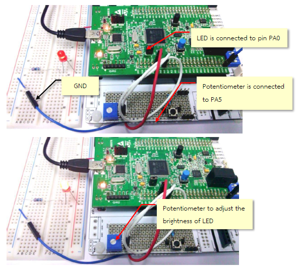
Figure 2‑6: Adjusting the brightness of LED with PWM
2.4 How to Use Advanced PWM Block
Advanced PWM block can be found in Simulink Library >> Waijung Blockset >> STM32F4 target >> On Peripheral Chip >> TIM and have the following characteristics.
This block is used for creating a Complementary PWM signal. Current driving circuit is of inverter type which controls the three phase motor and brushless motor.
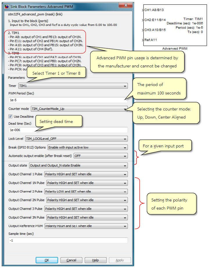
Figure 2‑7: Settings for advanced PWM block
2.5 The Complementary PWM Test Signal Generation
Objective
- Enable the users to use advance PWM block;
- To provide a comparison between complementary PWM and PWM signals;
- Enable the users to understand the meaning of dead-time.

Figure 2‑8: Simulink Model for generating complementary PWM signal
Figure 2‑8 shows a Simulink model for generating a complementary PWM signal from Timer 1 using advanced PWM block. The configuration of each channel is as follows.
- Output Channel 1 Pulse: Polarity HIGH and SET when idle
- Output Channel 1N Pulse: Polarity HIGH and RESET when idle
- Output Channel 2 Pulse: Polarity HIGH and SET when idle
- Output Channel 2N Pulse: Polarity HIGH and SET when idle
- Output Channel 3 Pulse: Polarity HIGH and SET when idle
- Output Channel 3N Pulse: Polarity LOW and RESET when idle
After downloading the model into STM32F4DISCOVERY, when pin PB12 is connected to GND, all channels will be in idle state. When the channel is set as “Set when idle”, then status will be “1”. If set as “Reset when idle”, then the status will be “0”. When pin PB12 is connected with VDD, each channel will generate a PWM and Complementary PWM signal as configured.
Figure 2‑9 shows TIM1_CH1N and TIM1_CH1N signals at the oscilloscope measured from pin PA8 and pin PB13 respectively. Both signals have frequency of 100 kHz and have following properties.
- When the status of TIM1_CH1 is High, TIM1_CH1N logic status is Low
- The Dead-time is 1 ms when the signal changes its logic state
- Dead-time is up to 10% of the signal period (10 uS), so the duty cycle of the TIM1_CH1 will be reduced to 15%
- Duty cycle of TIM1_CH1N signal is 100 – 25 = 75%. Due to dead-time, the measured duty cycle turned out to be 65%.
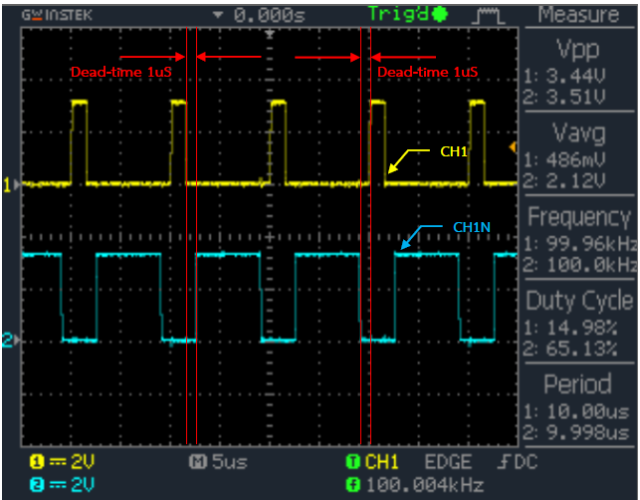
Figure 2‑9: Complementary PWM signal at Channel 1
Figure 2‑10 shows the signals from TIM1_CH2 and TIM1_CH2N from the oscilloscope which are measured from pin PE11 and pin PB14. Both signal frequencies are still 100 kHz but the duty cycle is reduced from 50% to 40%.
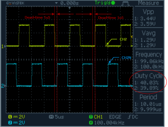
Figure 2‑10: Complementary PWM signal characteristics at Channel 2
Figure 2‑11 shows the signal from TIM1_CH3 and TIM1_CH3N from the oscilloscope which are measured from PA10 and PB15. TIM1_CH3N is set at low polarity.
The duty cycle (shown in Figure 2‑8) of TIM1_CH3 can be changed by rotating the Potentiometer connected with PA5. The duty cycle of TIM1_CH3 was adjusted to 70% (60% as measured by dead-time).
Duty cycle of TIM1_CH3N is 100 – 70 = 30%. Due to dead-time, duty cycle is 20%. When polarity signal is turned on, the measured duty cycle is 80% as shown in Figure 2‑11.
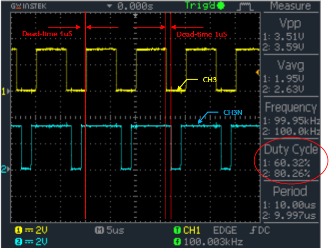
Figure 2‑11: Complementary PWM signal characteristics at Channel 3
3 Using TIM IRQ
3.1 Interrupt
Consider an example in which you are watching a movie at your home. Suddenly postman rings the bell of your home who came for the delivery of registered post. You need to stop the movie and go the gate to receiver the delivery from the postman. After receiving the delivery, you can re-start watching the movie from the point where you left. In the language of the microcontroller, we can say that bell from the postman was an event or interrupt sometimes called as interrupt function as Interrupt Service Routine (ISR).
STM32F407VGT6 Microcontroller is used in STM32F4DISCOVERY board. There are 82 sources of interrupts in the microcontroller which includes digital input signal, I2C SPI, UART and Timer etc.
There is a possibility that the more than 1 interrupt can occur at a given time. For example a program is running and there is an interrupt from UART and an interrupt from digital input of the microcontroller. To overcome this challenge, priority is assigned to each interrupt and interrupts are executed based on their priorities.
In this section, discussion is done on how to use TIM IRQ Block which utilizes timer value to make and interrupt and then start Interrupt Service Routine.
3.2 How to use Timer (Time base) IRQ?
Advanced PWM Block can be found in Simulink library >> Waijung Blockset >> STM32F4 target >> On Peripheral Chip >> TIM and have the following characteristics.

Figure 3‑1: Appearance and setting of Timer (Time base) IRQ Block
When timer is put in IRQ Block model, IRQ signal will be sent every sample time to activate the working in Function-Call Subsystem Block. Users can choose and put Function-Call Subsystem Block from the Library >> Simulink >> Ports and Subsystems.
The Limitation of this block is that it can be used to create interrupt other than using Timer 1 and Timer 8.
3.3 Example of TIM IRQ Block
Objectives:
- The user can use the Timer IRQ Block.
- To allow the users to understand the operation of Timer IRQ Block and Function-Call Subsystem
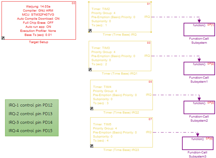
Figure 3‑2: Simulink Model for Time IRQ Block
Create a Simulink model as in Figure 3‑2 which have 4 set of timer IRQ blocks. Select TIM2 – TIM5 to be used as source of interrupt. IRQ signal will be sent to Function-Call Subsystem Block as shown in Figure 3‑3.
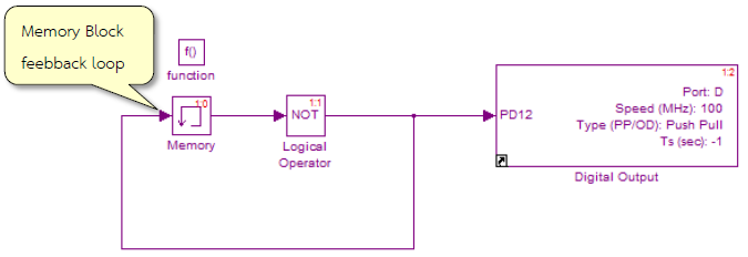
Figure 3‑3: Function-Call Subsystem Block (used in the experiment) Timer IRQ Block
When ‘Ctrl + J’ is pressed to observe the sample time, we can see that Function-Call subsystem block will be executed by Timer IRQ block only. Therefore, it is not possible to identify the accurate sample time (Asynchronous).
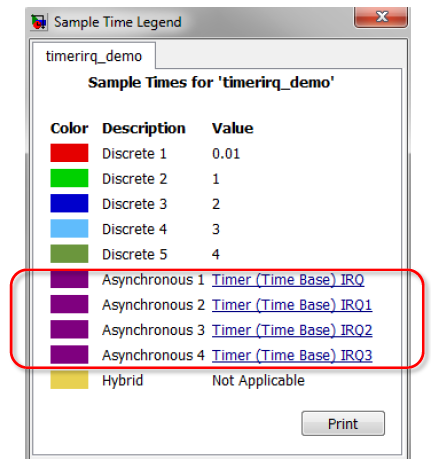
Figure 3‑4: Sample Time Legend window
Download model into STM32F4DISCOVERY board. LED1, LED2, LED3 and LED4 will blink 1, 2, 3 and 4 seconds respectively.
4 Using PWM Capture
4.1 Introduction
The pervious lesson tells that how user can generate the PWM signal by setting the properties of the signal such as pulse width, frequency etc. On the other hand, if the users want to measure the width or period of the PWM signal at the input, microcontroller’s timer can be used for detecting and counting the signal. This can be used for measuring the pulse ON period and frequency of the signal. When using the input capture mode for measuring the distance with ultrasonic module HC-SR04, the distance is calculated by measuring the echo time. This is shown in Figure 4‑1.
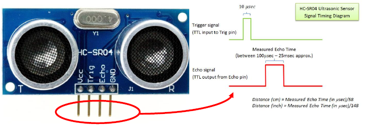
Figure 4‑1: Ultrasonic module signal characteristics of detecting objects
When working on the timer module in input capture mode, it uses 2 set of edge detection (IC1 and IC2). If IC1 is set to detect positive edge, IC2 will detect the negative edge. Figure 4‑2 shows an example of timer module in input capture mode that the interval of ON is 3 and OFF is 5. Measuring units depends on the frequency that has been set.
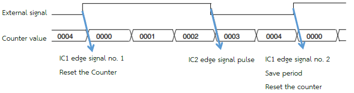
Figure 4‑2: Operating mode of Timer is Input Capture [1, p. 373]
4.2 How to use PWM Capture Block
PWM Capture block can be found in the Simulink Library >> Waijung Blockset >> STM32F4 target >> On Peripheral Chip >> TIM and have the following characteristics.
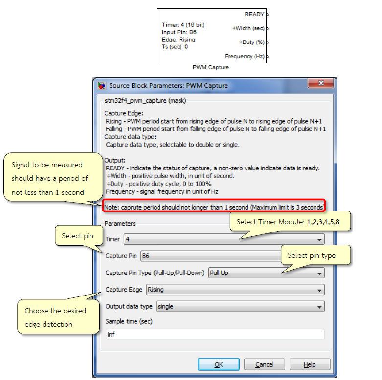
Figure 4‑3: Appearance and settings of the PWM Capture Block
For measuring the width of the digital signal, user need to choose between the rising or the falling edge as shown in Figure 4‑4.
By comparing the measured signal or rising edge or falling edge, the period of the signal can be calculated.
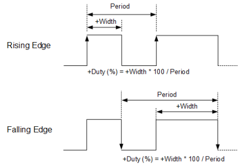
Figure 4‑4: Comparing the measured signal on rising and falling edge
4.3 Experiment of Measuring Pulse Width
Objective
- Enable the users to read the pulse width using PWM Capture Block.

Figure 4‑5: The experimental values of the pulse width
Figure 4‑5 shows the experimental setup. Pin PA0 is used for generating PWM signal. Potentiometer is connected with pin PA5 which can be used to adjust/change the duty cycle of PWM signal. The data is sent to the computer via aMG USB Converter-N board.
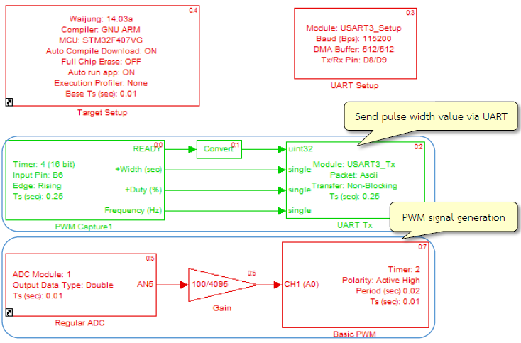
Figure 4‑6: Simulink model for reading the pulse width
Download the Simulink model on STM32F4DISCOVERY board. The frequency is PWM signal is 50 Hz i.e. period is 0.02 seconds. The signal will be sent to pin PB6 of PWM capture block for pulse width measurement. The measured value will be sent to UART-TX Block to post it after every 0.25 seconds.
Figure 4‑7 shows the received value of the pulse width, duty cycle and signal frequency. If the detector cannot measure the pulse width, for example – pin PB6 is directly connected to voltage supply or GND, the output will be zero.
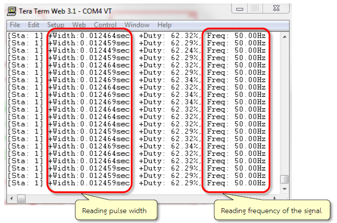
Figure 4‑7: Reading the pulse width from TeraTerm program
5 References
- STMicroelectronics, “RM0090: STM32F40xxx Reference Manual [Online],” 2013.
- STMicroelectronics, “STM32 F407xx Datasheet-production data [Online],” 2013.