Forums » Req. WJ2(Zynq-7000) support »
 uart_demo1 / usart_demo2
Added by Johan Henning over 3 years ago
Please specify the maximum path length, this avoids trial and error. Is the path length including or excluding the filename?
The documentation in the model says:
Note: Before trying the demo, please copy the demo model file and the hardware reference file(.xsa file) to a shoter file path directory since there is a path length limitation in Xilinx tools
usart_demo2 does not work. After sending the commandbaudrate=19200<LF> and sending some data no data is received any more
A few typo's:
shoter -> shorter
chnage -> change
Replies (11)
RE: uart_demo1 / usart_demo2
-
Added by Shawn Sebastian Pulle (ฌอน) over 3 years ago
Hi Johan,
Thank you for the feedback.
Xilinx have not mentioned the maximum path length for their tools. But we are currently testing with trial and error from our end to give the users a specific value that would help avoid trial and error from the users end.
This is still under testing and the result will be mentioned where applicable in future releases.
From our testing so far, the model file name length also applies to the path length limitation.
The uart_demo2 is working as intended. Please follow the steps mentioned under "What should be happening?" section of the demo information.
The baud rate is set to 115200 by default.
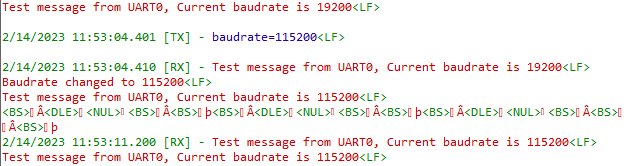
1. Please set the baudrate of your serial monitor to 115200 first and send the desired baud rate. For example baudrate=19200<LF>.
2. Next change the baud rate of the serial monitor to 19200 and send some dummy data then the baud rate will be set to 19200.
RE: uart_demo1 / usart_demo2
-
Added by Johan Henning over 3 years ago
Hello Shawn,
Thanks for your reply. I can go from the initial 115200 to for example 9600 baud. But I cannot go back to 115200 baud. Does that work at your side?
I do not like the complicated way the changing of baudrate works. It now works by generating a framing error and by sending some characters with the 'wrong baudrate' that will cause a framing error. And it uses two data store locations (baudrate and pre_baudrate).
I would prefer a much simpler model and I tried that but without success so far. Can you have a look at it and explain why this model does not work (uart_demo2c)?
My idea was:
1. Enable is set to 1 initially
2. The enabled subsystem initializes the UART and resets Enable to 0
3. When a new baudrate is invoked by the command "baudrate=xxx" the new baudrate is stored in the data store and the Enable data store is set to 1. This re-initializes the UART
I worked in the past with a third party system that starts up at 9600 baud. You can send it a command to switch to a higher baudrate and from then on you have to use the higher baudrate. Sending 'dummy' characters to switch baudrate is not a clean way of communicating. So in my opinion there should be a cleaner way to change baudrate 'on the fly'. Maybe an extra toolkit block is the solution in which the communication parameters can be programmed and re-programmed.
Regards,
johan.
| uart_demo2c.slx | uart_demo2c.slx | 38.2 KB |
RE: uart_demo1 / usart_demo2
-
Added by Shawn Sebastian Pulle (ฌอน) over 3 years ago
Hi Johan,
Not being able to go back to 115200 baud rate is expected behavior from the demo. The demo was created as a way to highlight and familiarize the user with the "interrupt" triggering feature of the block set.
It was not intended as a demo where the user can change the baud rate. The baud rate was changed to show one of the possibilities that could be achieved once the interrupt has been triggered.
But as pointed by you, it is clear this intention of the demo has not clearly come across to the end user. We will modify the description of the demo to clearly state this fact without creating confusion to the user.
We would be grateful if you would be so kind to give your feedback as well on this matter.
Regarding a demo that can change the baud rate on the fly, we can add a demo that lets the user change baud rates in a future release if you think that is a useful addition to this block set.
Regarding uart_demo2c.slx (the file attached by you), the reason it does not work beyond the initial uart write command is that the Setup block is not being retriggered on time to receive the data. When the enable subsystem is off, the uart setup is disabled. This also means uart is not working when the setup is not enabled.
In this model, when the console is sending uart data to the board, uart module is disabled. Therefore it is never going to be enabled, since reenabling code is tied to the receive block at the moment. The logic of the enable should be reconstructed to make sure it enables the setup block every iteration of the loop, regardless of receiving uart communication.
This behaviour of the setup block is mentioned in our documentation under UART block behavior .
To change the baud rate of the UART module in the runtime using an input port, the UART Setup block should be placed in an Enabled subsystem. Once the subsystem is disabled and enabled the baud rate will be changed to the value which is specified in the input port. The UART module can be disabled (stop the communication) by disabling the Enabled subsystem of the relevant UART Setup block.
Please let us know if you have anymore feedback on this issue.
Best Regards,
Shawn
RE: uart_demo1 / usart_demo2
-
Added by Johan Henning over 3 years ago
Hello Shawn,
Thanks for your reply. That was helpful.
A few remarks, questions and suggestions:
1. To demonstrate the interrupt possibility I would suggest to offer an example that turns on an LED when a framing, parity or overrun error occurs. I don't like the approach to (mis)use an error (framing error) to build functionality (changing the baudrate).
2. I really do like a demo program to switch baudrates on the fly. I understand now after your explanation why my attempt did not work, I created another model. See attached. It does change the baudrate from 115200 to the value that is send via the command "baudrate=xxx", but after that I cannot change it back to 115200 or to another value (although I managed one time to do it after several tries). Do you understand why this is? When I type in "baudrate=9600" the terminal program shows: "Baudrate changed to 9600", but when I type another value (e.g. "baudrate=115200") there is no reply. When I type "baudrate=9601" is shows two lines: "Baudrate changed to 9601" and then "Baudrate changed to 9600". Very strange...
3. I think it would be nice to offer the "change baudrate demo" also for the internal uart (UART_1). That makes it possible to run the demo without connecting to the serial port via a USBtoSerial device. I created uart_demo3b for that, it has the same behavior as uart_demo3.
Regards,
johan.
| uart_demo3b.slx | uart_demo3b.slx | 44.3 KB | for internal UART | ||
| uart_demo3.slx | uart_demo3.slx | 41.5 KB | Change baudrate on the fly-try |
RE: uart_demo1 / usart_demo2
-
Added by Shawn Sebastian Pulle (ฌอน) over 3 years ago
Hi Johan,
Thank you for the helpful suggestions and feedback.
1. We understand your concern on this issue. We will discuss internally and rework demo2 as necessary.
2. I tested for the behavior you mentioned using the attached uart_demo3b.slx. I did not run into any of the mentioned issues. I even tried several custom baud rates and was not able to see any abnormal results. I also have no problems to change back to 115200 baudrate. Is it possibly an issue related to the usb to uart converter you are using?
3. While it is possible to have one of the demos to be configured to UART_1, we generally configure demos to work on the most default device id's unless it is unavoidable. This is due to the fact that even though the demos are tested with zybo z7-20 and provides a .xsa file for zybo z7-20, we are expecting users who are not using this specific board to still be able to run these demos with minimum effort. Such a user would be able to configure their own .xsa file by editing our xsa, using the tcl file provided with each demo. Currently we are in the process of writing a "how to" guide on this step (for users who are not using the zybo z7-20), which will be added to the user manual under general information.
Best Regards,
Shawn
RE: uart_demo1 / usart_demo2
-
Added by Johan Henning over 3 years ago
Hello Shawn,
1. Another reason for a 'universal' .xsa file :-)
2. After some more testing I found out that my uart_demo3(b).slx works when sending the change baudrate command twice ( "baudrate=xxx<LF>"). After the first attempt nothing happens, after the second attempt the baudrate is changed. Does it always work in your system after the first time you sent a change baudrate command? Or - as in my system - after the second attempt?
3. Ok, I understand. My point (opinion) was: I would be nice if the demos could run with as little hardware and hassle as possible. When using USART_0 you need an additional USB-to-serial converter and solder a few wires to PMOD JF. When using USART_1 no extra stuff is neccessary, only the Zybo board.
Regards,
johan.
RE: uart_demo1 / usart_demo2
-
Added by Shawn Sebastian Pulle (ฌอน) over 3 years ago
Hi Johan,
Thank you for the feedback.
I did not have to send the message twice for the baud rate to switch. I am using the docklight v2.3 software.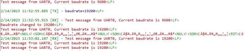
We will keep discussing internally on the UART1 feedback. With more research on available boards in the market, we can hopefully come to a convenient solution to this problem that covers multiple boards.
Best Regards
Shawn
RE: uart_demo1 / usart_demo2
-
Added by Johan Henning over 3 years ago
Hello Shawn,
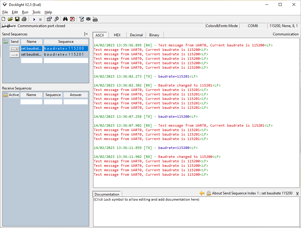
I installed Docklight 2.3. This does not solve the problem. See screenshot. Steps:
1. It starts at 115200 baud
2. Command to switch to 115201 baud: works correctly (baudrate changed message and displaying the new baudrate)
3. Command to switch to 115200 baud: does not work (no baudrate changed message and displaying the old baudrate)
4. Command to switch to 115200 baud: works correctly now (baudrate changed message and displaying the new baudrate)
Can it be a timing issue? Maybe the speed of my PC has something to do with it?
I am using Windows 11 but I cannot imagin that that has something to do with it. I have the same behavior with Realterm and with Putty.
I tried increasing the delay in the Enable signal but no effect.
I tried commenting out the code that writes a '0' in the Enable data store. If I do that the "baud rate changed" messages appear every time I sent the command. Of course the baudrate does not change then because the part of the model that takes care of that is not activated because the Enable signal remains a '1'.
Then I replaced the data store read of the enable signal with a constant of '1'. Same behavior.
Are you using the same version of the toolkit as I do? Can I sent you my binary file (where is it?) so that you can try that on your Zybo?
So I am lost. The first time after running the program the change baudrate works fine, after that I have to sent the change baudrate command twice, the first one is ignored, the second one works, Any idea's?
Regards,
johan.
RE: uart_demo1 / usart_demo2
-
Added by Shawn Sebastian Pulle (ฌอน) over 3 years ago
Hi Johan,
An update to the block set is planned to be released at the end of next week.
We think it would be better to revisit this issue after this update. Please wait for the update if possible.
If the issue persists after the update, please send us your .bit file along with the .elf file
RE: uart_demo1 / usart_demo2
-
Added by Johan Henning over 3 years ago
Ok, I''ll wait and see if the problem is also in that version and let you know.
I tried several other things but without success. Amongst others splitting up the receiving of the new baudrate and switching to the new baudrate. I have the feeling that - after disabling and re-enabling the serial port setup - the last received command is remaining in the receive buffer and processed again. We will see.